5 connecting to relays – Measurement Computing CIO-RELAY08 User Manual
Page 12
5 CONNECTING TO RELAYS
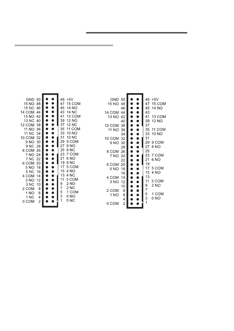
5.1 I/O CONNECTOR DIAGRAMS
The CIO-RELAY08 and CIO-RELAY16 boards use a single 50-pin connector for
signal interfacing. The CIO-RELAY24 and CIO-RELAY32 use two, 50-pin
connectors. The pin-outs of the connectors are shown in Figures 5-1 through 5-4.
Figure 5-1. CIO-RELAY08 & 16
Figure 5-2. CIO-RELAY08/M & 16/M
Connector
Connector
PINS corresponding to relays 8 through 15 are not connected on the RELAY08
version (Figure 5-1). Note that the form A relays used on the /M versions have
NO and COM connections only (Figure 5-2).
WARNING!
High voltages will be present on the CIO-RELAY boards when you have connected
high voltage inputs or outputs to the CIO-RELAY connector. Use extreme caution!
Never handle the CIO-RELAY board when high voltage signals are connected to it.
DO NOT REMOVE THE PROTECTIVE PLATES FROM THE BOARD
.
8