Measurement Computing CIO-TERM100_DST User Manual
Page 4
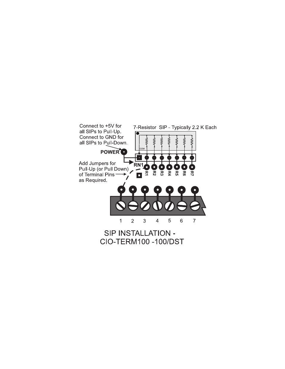
The board has 14 open mounting positions where 8-pin, 7-resistor Single Inline Packages (SIPs) can be
installed when pull-up (or pull-down) resistors are necessary or desirable. The common terminals on the
SIPs are all common to each other on the board. The board connection point is labeled “POWER”.
Thus, if the POWER point on the board is tied to +5VDC, any SIP installed and jumper-wired to screw
terminals will have those pins pulled high (Figure 1-3).
Alternatively, if the POWER point is tied to Ground, any (and all) installed SIPs resistors will pull their
associated screw terminals to ground.
We recommend using 2.2Kohm resistors for pull-up or pull-down. You can obtain these from us: the part
number is 2.2K*7PU.
NOTE: SIPs are not connected to screw terminals by board etch. After a SIP is installed, you must
install jumpers to each resistor from the screw terminals as required.
Figure 1-3. SIP Installation
Most boards that you would use this terminal board with have SIP locations also. Either location can be
used with equal efficiency. However, it can be useful to have both. If one or m ore digital lines do not
require termination, there is an adv antage to using the resistor locations on the CI O-TERM100 since the
resistors are individually jumpered to each digital IO line.
If you are unfamiliar with pull-up/pull-down resistor theory, refer to the manual for the Digital I/O board.
See Figure 1-4 and 1-5 for schematics of the CIO-TERM100 and CIO-TERM100/DST terminal boards.
2