0 software installation, 0 hardware installation – Measurement Computing CIO-INT-32 User Manual
Page 6
2.0 SOFTWARE INSTALLATION
In order to easily test your installation, it is recommended that you install InstaCal, the
installation, calibration and test utility that was supplied with your board. Refer to the
Software Installation Manual for information on the initial setup, loading, and
installation of InstaCal and optional Universal Library software.
3.0 HARDWARE INSTALLATION
3.1 BASE ADDRESS
The CIO-INT32 employs the PC bus for power, communications and data transfer.
As such it draws power from the PC, monitors the address lines and control signals
and responds to it's I/O address, and it receives and places data on the 8 data lines. If
enabled, it has interrupt capability.
The BASE address is the most important user selectable bus related feature of the
CIO-INT32. The base address is the location that software writes to and reads from
when communicating with the CIO-INT32.
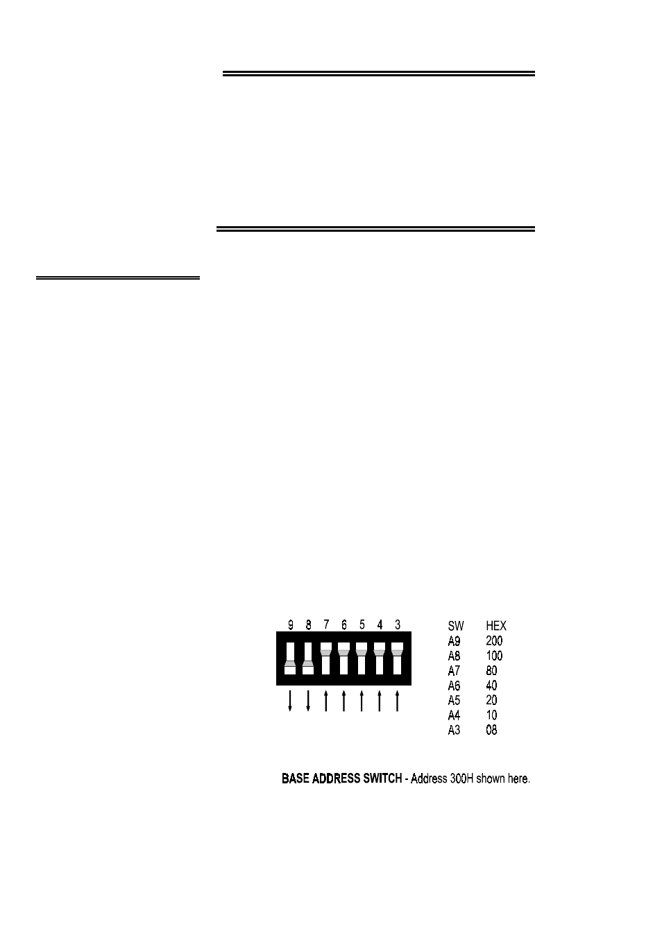
The base address switch is the means for setting the base address. Each switch
position corresponds to one of the PC bus address lines. By placing the switch down,
the CIO-INT32 address decode logic is instructed to respond to that address bit.
A complete address is constructed by calculating the HEX or decimal number which
corresponds to all the address bits
the CIO-INT32 has been instructed
to respond to.
For example, shown to the right are
address 9 and 8 ON, all others
OFF.
Address 9 = 200H (512D) and
address 8 = 100H (256D), when
added together they equal 300H
(768D).
2