Measurement Computing CIO-INT-32 User Manual
Page 16
electrical environment; and unpredictable! This is why it often appears that the Z8536
has gone 'high' after power up. The result is that the controlled device gets turned on!
That is why you need pull up/down resistors.
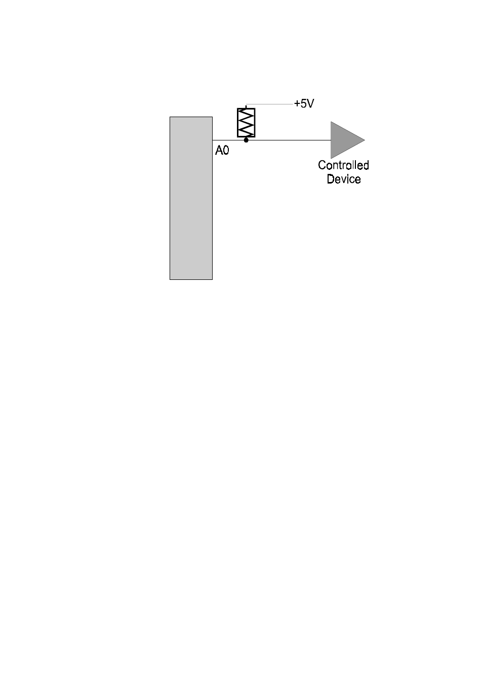
Shown here is one Z8536
digital output with a pull-up
resistor attached.
The pull-up resistor provides
a reference to +5V while its
value of 10,000 ohms allows
very little current to flow
through the circuit.
If the Z8536 is reset and
enters high impedance input,
the line is pulled high. At that
point, both the Z8536 AND
the device being controlled
will sense a high signal.
If the Z8536 is in output
mode, the Z8536 has more than enough power to over ride the pull-up resistor's high
signal and drive the line to 0 volts. If the Z8536 asserts a high signal, the pull up
resistor guaranties that the line goes to +5V.
Of course, a pull-down resistor accomplishes the same task except that the line is
pulled low when the Z8536 is reset. The Z8536 has more than enough power to drive
the line high.
The CIO-INT32 boards are equipped with positions for pull-up/down resistors Single
Inline Packages (SIPs). The positions are marked A, B and C and are located beside
the Z8536.
A 10 Kohm, 8-resistor SIP has 10K resistors all connected one side to a single
common point and the other, each to a pin protruding from the SIP. The common line
to which all resistor are connected also protrudes from the SIP. The common line is
marked with a dot and is at one end of the SIP.
The SIP may be installed as pull-up or pull-down. At each location, A, B & C there
are 10 holes in a line. One end of the line is +5V, the other end is GND. They are so
marked. The eight holes in the middle are connected to the eight lines of the port, A,
B, or C.
12
10K
Z8536