Functional details, Signal level control, Chapter 3 – Measurement Computing CIO-DIO48 User Manual
Page 13: Through, Figure 6, Connects to +5v. the end marked
Chapter 3
Functional Details
Signal level control
The digital I/O bits on the CIO-DIO48 are 8255 CMOS TTL. The 82C55 digital I/O chip initializes all ports as
inputs on power- up and reset. A TTL input is a high impedance input. If you connect another TTL input device
to the 82C55 it could be turned ON or OFF every time the 82C55 is reset.
All I/O bits are set to input mode on power up and reset. If you are using the board to control items that must be
OFF on reset, install pull-down resistors. The CIO-DIO48 has open locations where you can install Single
Inline Packages (SIP) resistor networks in either pull-up or pull-down configurations.
You can install pull-up and pull-down resistor SIP packs at each port. The positions are labeled
RN1
through
RN6
on the board. When installed, the SIP establishes either a high or low logic level at each of the I/O lines on
the port.
To safeguard against unwanted signal levels, the devices being controlled by the CIO-DIO48 board should be
tied low or high as required by a 2.2K
Ω resistor. In a 2.2K eight-resistor SIP pack, one side of all of the
resistors is connected to a single common point and brought out to a pin. The common line, usually marked
with a dot or line, is at one end of the SIP. The remaining resistor ends are brought out to the other eight pins
(refer to Figure 5).
2.2KOhm SIP
Dot indicates the
common line
(LO or HI)
I/O Lines
Figure 5. Eight-resistor SIP schematic
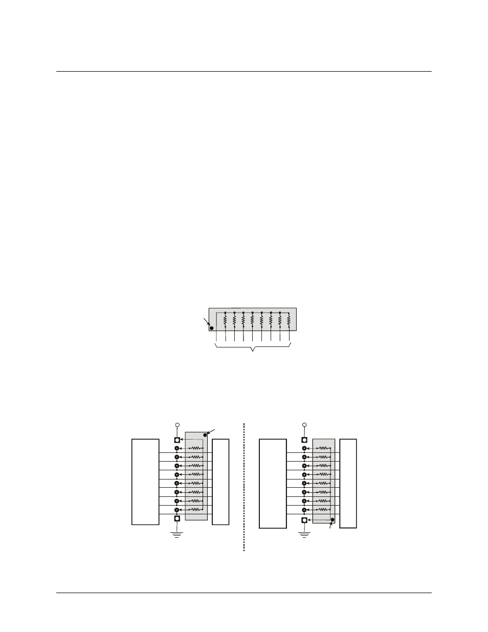
Figure 6. Pull-up and pull-down resistor SIPs schematic
shows a schematic of an SIP installed in both the pull-up and pull-down positions. Each port provides
10 holes in a line. The end labeled
HI
connects to +5V. The end marked
LO
connects to GND. The eight holes
in the middle (n0 –n7) connect to the eight lines of the Port, A, B or C.
2.2 K SIP installed for pull-up
2.2 K SIP
Dot
+5 VDC
HI
LO
(GND)
n7
Us
e
r Con
n
e
c
to
r
D
igi
ta
l I/O
L
in
e
s
n5
n4
n3
n2
n1
n0
n6
COM
Digital
I/O
Port
n = A, B, or C
2.2 K SIP
Dot
+5 VDC
HI
LO
(GND)
n7
Us
e
r Con
n
e
c
to
r
D
igi
ta
l I/O
L
in
e
s
n5
n4
n3
n2
n1
n0
n6
COM
2.2 K SIP installed for pull-down
Digital
I/O
Port
n = A, B, or C
1
3