Pinout – main i/o connector, Cabling – Measurement Computing CIO-DIO48 User Manual
Page 11
CIO-DIO48 User's Guide
Installing the CIO-DIO48
Pinout – main I/O connector
The CIO-DIO48 connector (P1) is a 50-pin male shrouded header connector that is accessible through the
PC/AT expansion bracket.
GND
50
FIRSTPORTC Bit 0
48
FIRSTPORTC Bit 2
46
FIRSTPORTC Bit 4
44
FIRSTPORTC Bit 6
42
FIRSTPORTB Bit 0
40
FIRSTPORTB Bit 2
38
FIRSTPORTB Bit 4
36
FIRSTPORTB Bit 6
34
FIRSTPORTA Bit 0
32
FIRSTPORTA Bit 2
30
FIRSTPORTA Bit 4
28
FIRSTPORTA Bit 6
26
SECONDPORTC Bit 0
24
SECONDPORTC Bit 2
22
SECONDPORTC Bit 4
20
SECONDPORTC Bit 6
18
SECONDPORTB Bit 0
16
SECONDPORTB Bit 2
14
SECONDPORTB Bit 4
12
SECONDPORTB Bit 6
10
SECONDPORTA Bit 0
8
SECONDPORTA Bit 2
6
SECONDPORTA Bit 4
4
SECONDPORTA Bit 6
2
49
+5V
47
FIRSTPORTC Bit 1
45
FIRSTPORTC Bit 3
43
FIRSTPORTC Bit 5
41
FIRSTPORTC Bit 7
39
FIRSTPORTB Bit 1
37
FIRSTPORTB Bit 3
35
FIRSTPORTB Bit 5
33
FIRSTPORTB Bit 7
31
FIRSTPORTA Bit 1
29
FIRSTPORTA Bit 3
27
FIRSTPORTA Bit 5
25
FIRSTPORTA Bit 7
23
SECONDPORTC Bit 1
21
SECONDPORTC Bit 3
19
SECONDPORTC Bit 5
17
SECONDPORTC Bit 7
15
SECONDPORTB Bit 1
13
SECONDPORTB Bit 3
11
SECONDPORTB Bit 5
9
SECONDPORTB Bit 7
7
SECONDPORTA Bit 1
5
SECONDPORTA Bit 3
3
SECONDPORTA Bit 5
1
SECONDPORTA Bit 7
Figure 3. I/O connector pin-out
All the digital inputs and outputs are TTL. Under normal operating conditions, the voltages on the I/O pins
range from near 0 volts for the low state, to near 5 volts for the high state. The voltages and currents of external
devices usually exceed these values. Because of this, external relays are usually employed to handle higher
current and voltage loads.
In addition to load matching, digital signal sources often need to be filtered or "de-bounced". Refer to the Guide
to Signal Connections for information on digital interfacing. This document is available at
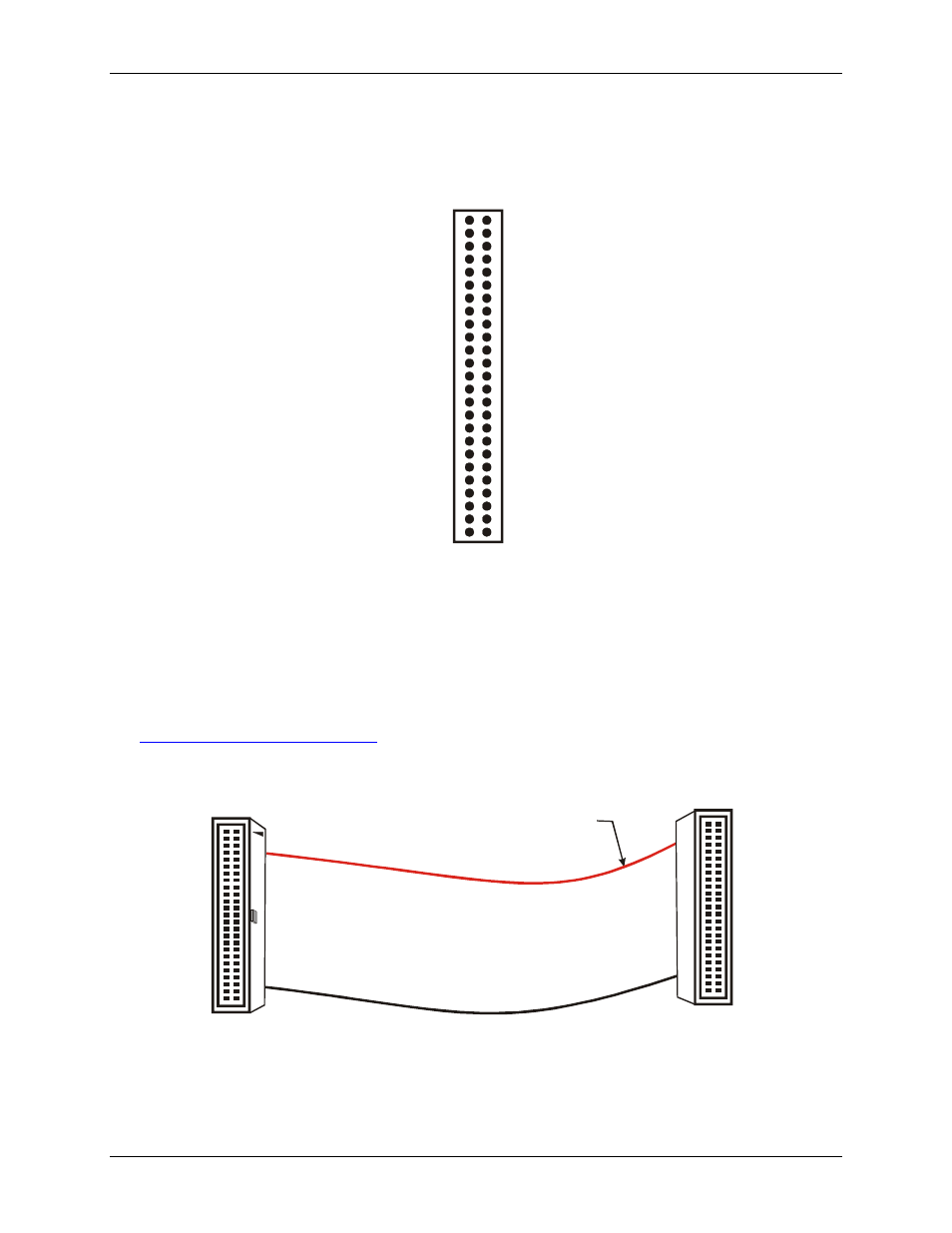
Cabling
The red stripe
identifies pin # 1
50-pin Female
IDC connector
50-pin Female
IDC Connector
1
2
49
50
2
50
1
49
Figure 4. C50FF-x cable
1
1