4 connector pin-out diagrams – Measurement Computing CIO-DI48 User Manual
Page 10
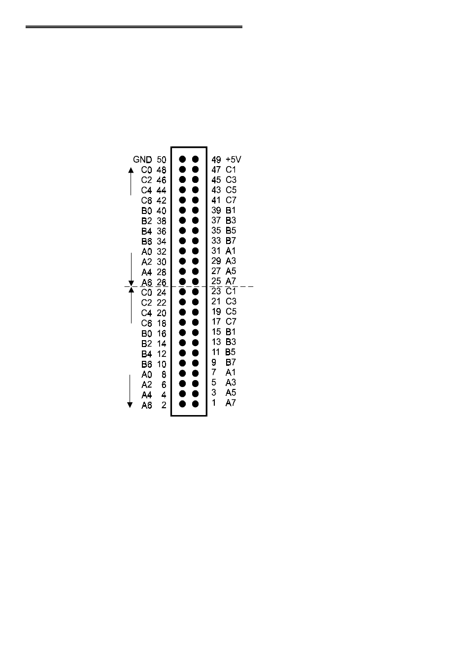
4.4 CONNECTOR PIN-OUT DIAGRAMS
The CIO-DI## series boards u se 50-pin header-type connector(s) mounted on the
board that are accessible from the rear of the PC through the expansion backplate.
O
The CIO-DI48 has one connector (Figure 4-2).
O
The CIO-DI96 has two connectors (Figure 4-3).
O
The CIO-DI192 has four connectors Figure 4-4).
Figure 4-2. CIO-DI48 Connector Pin-Out & Register Assignments
NOTE: The input signals are direct connections to a digital buffer chip.
The connector accepts female 50-pin header type connectors, such as th ose on the
C50FF-2, 2 foot cable with connectors.
6
B
A
SE +
0,
+1,
a
n
d +
2
P
O
RT
2
P
O
RT
1
B
A
SE +
4,
+5,
a
n
d +
6