Individual / simultaneous transfer jumper, Installing the cio-dda06/jr – Measurement Computing CIO-DDA06/JR User Manual
Page 10
CIO-DDA06/JR User's Guide Installing the CIO-DDA06/JR
In the default configuration shown in Fi
, addresses 9 and 8 are DOWN, and all others are UP.
Address 9
= 200 hex (512 decimal), and address 8 = 100 hex (256 decimal). When added together they equal
300 hex (768 decimal).
Disregard the numbers printed on the switch
When setting the base address, refer to the numbers printed in white on the printed circuit board.
Individual / simultaneous transfer jumper
The analog outputs can be jumpered so that new output data is held until several DACs are loaded with new
digital data. Then, as a group, the data for each DAC is simultaneously transferred and the DAC voltage
outputs are updated when any of the addresses BASE + 0 to BASE + B are read.
The analog output chips are dual DACs (two analog outputs per chip). A single jumper sets both DACs on a
single chip to be either simultaneously transferred on a read, or individually updated when the control register
is written. The jumpers are labeled J1, J2 or J3 on the board.
J1 sets the transfer mode for channels 0 and 1.
J2 sets the transfer mode for channels 2 and 3.
J3 sets the transfer mode for channels 4 and 5.
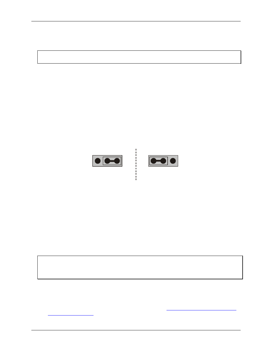
Figure 3 shows the jumper block configured for each update mode.
Individual updates
per channel
XFER
Jx
XFER
UPDATE
Jx
Simultaneous updates
of both channel
XFER
Jx
XFER
UPDATE
Jx
Figure 3. Individual / simultaneous update jumper
When the jumpers are in the
XFER
position, new output data is held until one or more DACs have been
loaded with new digital data. The new data transfers to the voltage outputs as a group. The simultaneous
transfers occur when any of the CIO-DDA06/JR addresses are read (and the jumpers are in the
XFER
position).
When the jumpers are in the
UPDATE ##
position, the DAC channel pair is individually updated when the
control register is written.
Installing the CIO-DDA06/JR
After you configure the board's switches and jumpers, you can install the CIO-DDA06/JR into your computer.
To install your board, follow the steps below.
Install the MCC DAQ software before you install your board
The driver needed to run your board is installed with the MCC DAQ software. Therefore, you need to install
the MCC DAQ software before you install your board. Refer to the Quick Start Guide for instructions on
installing the software.
1.
2.
3.
Turn your computer off, open it up, and insert your board into an available ISA slot.
Close your computer and turn it on.
To test your installation and configure your board, run the InstaCal utility you installed in the previous
section. Refer to the Quick Start Guide that came with your board
for information on how to initially set up and load InstaCal.
10