Diff/single, Installing the cio-das48-pga, Connecting the board for i/o operations – Measurement Computing CIO-DAS48-PGA User Manual
Page 11: Connectors, cables – main i/o connector, 48 single 24 diff
CIO-DAS48-PGA User's Guide
Installing the CIO-DAS48-PGA
11
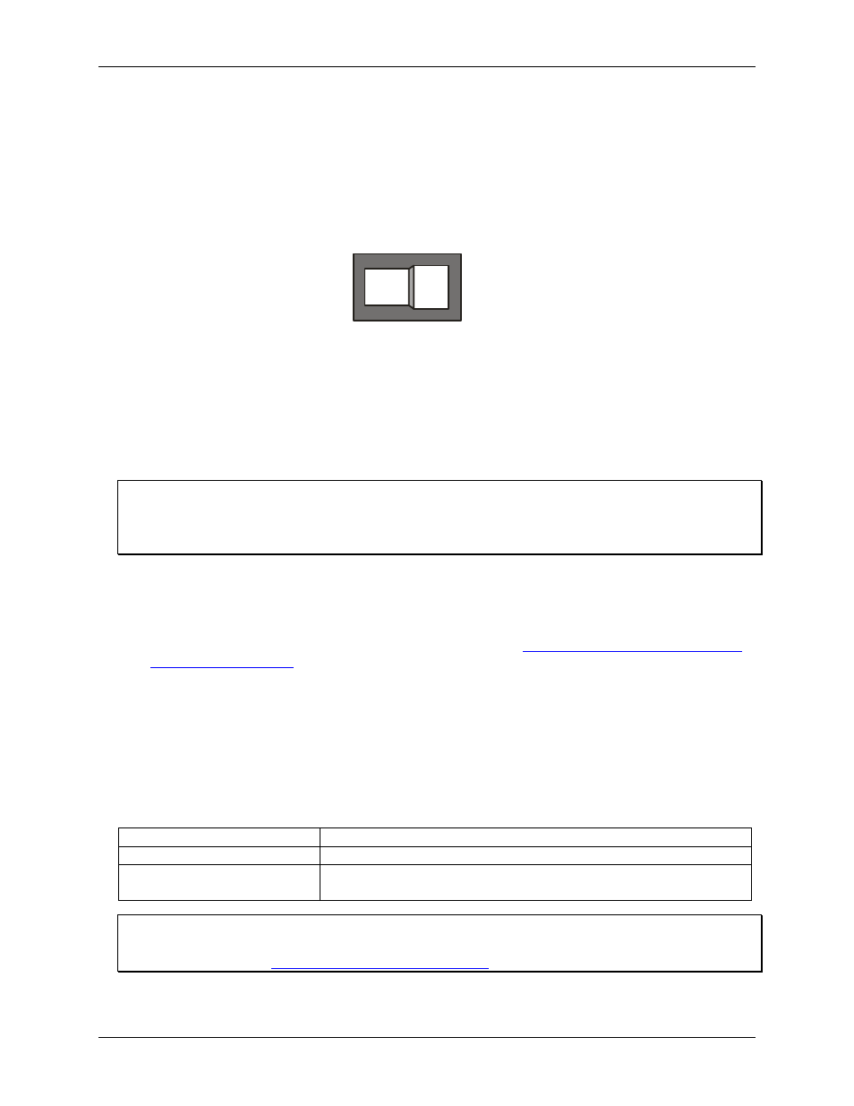
DIFF/SINGLE
The differential/single ended mode switch (Figure 4) sets board logic for 48 single-ended channels (
48 SINGLE
position) or 24 differential channels (
24 DIFF
position). If the board is configured for current measurements, set
the V-I jumper to
I
, and then set the input mode switch to
24 DIFF
.
In voltage mode, (V-I jumper "V" position), the board can be used for either single-ended or differential
voltage measurements.
48
SINGLE
24
DIFF
Figure 4. Input mode switch
Installing the CIO-DAS48-PGA
After you configure the board's switches and jumpers, you can install the CIO-DAS48-PGA into your
computer. To install your board, follow the steps below.
Install the MCC DAQ software before you install your board
The driver needed to run your board is installed with the MCC DAQ software. Therefore, you need to install
the MCC DAQ software before you install your board. Refer to the Quick Start Guide for instructions on
installing the software.
1. Turn your computer off, open it up, and insert your board into an available ISA slot.
2. Close your computer and turn it on.
3. To test your installation and configure your board, run the InstaCal utility you installed in the previous
section. Refer to the Quick Start Guide that came with your boar
for information on how to initially set up and load InstaCal.
Connecting the board for I/O operations
Connectors, cables
– main I/O connector
The table below lists the board connector, applicable cables, and compatible accessory products.
Board connector, cables, and accessory equipment
Connector type
50-pin header connector
Compatible cable
C50FF-x
Compatible accessory products with
the C50FF-x cable
CIO-MINI50
CIO-SPADE50
Information on signal connections
General information regarding signal connection and configuration is available in the Guide to Signal
Connections (availa
.