6 register architecture – Measurement Computing CIO-DAS08/JR/16 User Manual
Page 8
6 REGISTER ARCHITECTURE
All of the programmable functions are accessible through the control and data registers, which are described here. We recommend
programming with the Universal Library and not by direct register programming.
6.1 REGISTER LAYOUT
The board is controlled and monitored by writing to and/or reading from eight consecutive 8-bit I/O addresses. The first address, or
BASE ADDRESS, is determined by setting a bank of DIP switches on the board.
A register is easy to read and write to. Most often, register manipulation is best left to ASSEMBLY language programs as most of the
board’s possible functions are implemented in easy to use Universal Library routines. Note that an X is an unspecified bit. There is no
function associated with that bit position. All X bits should be masked out of reads.
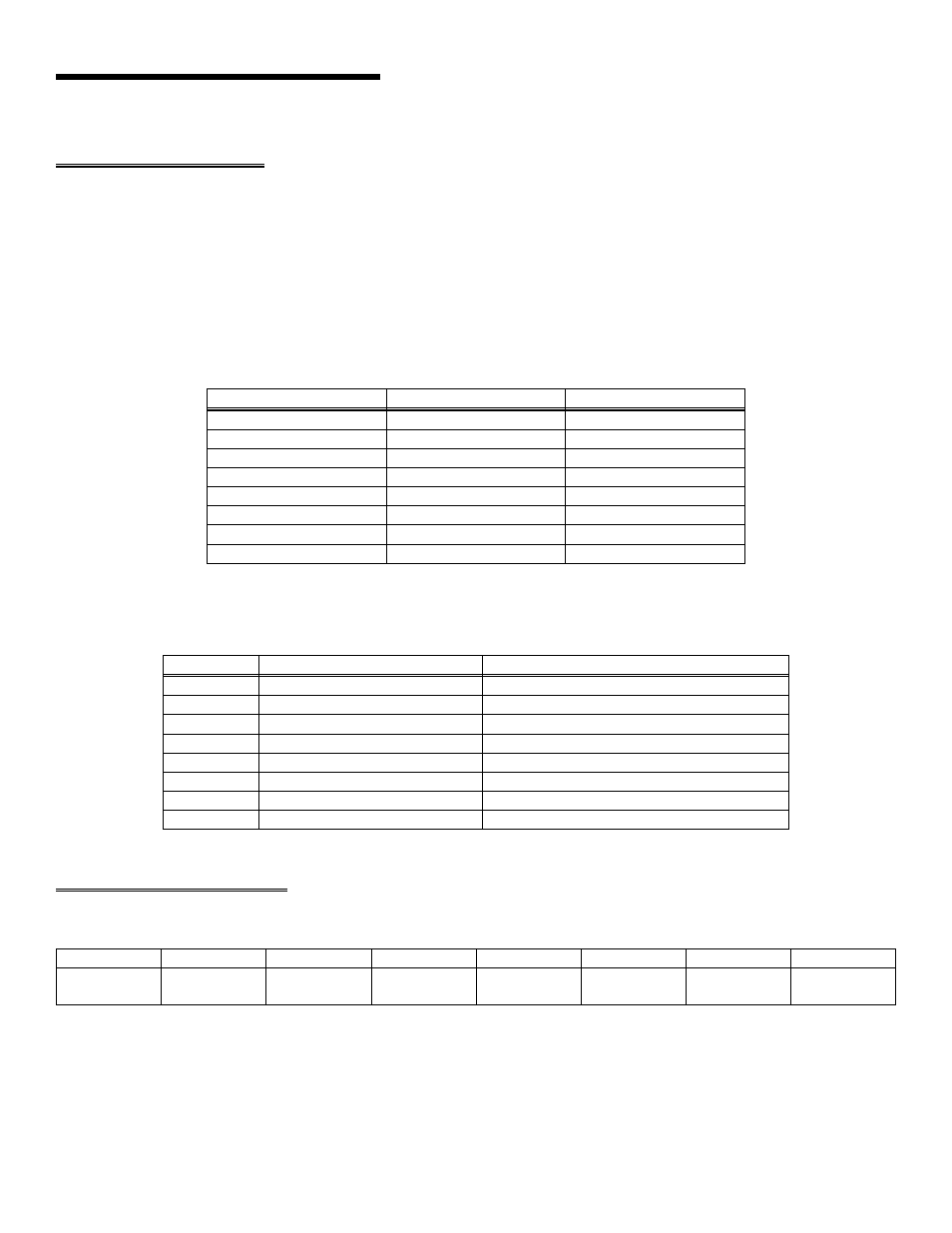
To write to or read from a register in decimal or HEX, the following weights apply:
Table 6-1. Bit Weights
80
128
7
40
64
6
20
32
5
10
16
4
8
8
3
4
4
2
2
2
1
1
1
0
HEX VALUE
DECIMAL VALUE
BIT POSITION
The registers and their function are listed on the following table. Within each register are 8 bits which may constitute a byte of data or
eight individual bit set/read functions.
Table 6-2. Board Registers
D/A 1 MSB ( CIO-DAS08/JR/16-AO only)
BASE + 7
D/A 1 LSB ( CIO-DAS08/JR/16-AO only)
BASE + 6
D/A 0 MSB ( CIO-DAS08/JR/16-AO only)
BASE + 5
D/A 0 LSB ( CIO-DAS08/JR/16-AO only)
BASE + 4
Digital output, 8 bits
Digital input, 8 bits
BASE + 3
Set A/D channel
A/D status & MUX Address
BASE + 2
Start 16 bit A/D conversion
A/D Bits 0 (MSB) - 7
BASE + 1
None
A/D Bits 8 - 15 (LSB)
BASE
WRITE FUNCTION
READ FUNCTION
ADDRESS
6.2 A/D DATA REGISTERS
BASE ADDRESS
A/D15
LSB
A/D14
A/D13
A/D12
A/D11
A/D10
A/D9
A/D8
0
1
2
3
4
5
6
7
READ ONLY
This register contains the least-significant eight bits of the analog input data from the A/D converter. These eight bits of analog input
data are combined with the eight bits of analog input data in BASE + 1, forming a complete 16-bit number.
The data is in the format 0 = minus full scale. 65535 = +FS.
4