Cabling, Field wiring, signal termination, and conditioning – Measurement Computing CIO-DAC08 User Manual
Page 14
CIO-DAC08 User's Guide
Installing the CIO-DAC08
The analog outputs of the CIO-DAC08 are two-wire hook-ups. Always use low-level ground (LLGND) as the
ground reference for all analog hook-ups.
Cabling
20
1
37
19
20
1
37
19
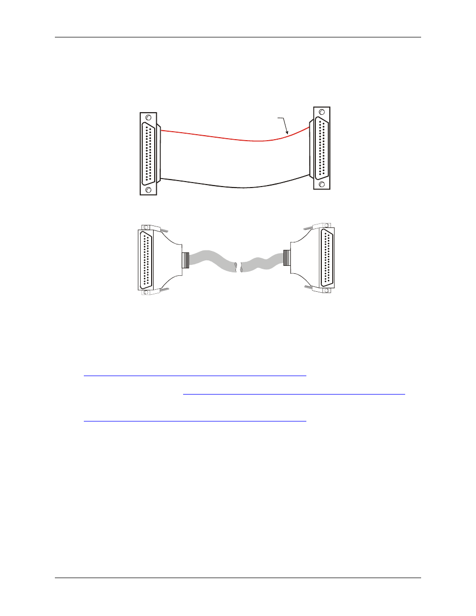
The red stripe
identifies pin # 1
Figure 7. C37FF-x cable
20
1
37
19
20
1
37
19
Figure 8. C37FFS-x cable
Field wiring, signal termination, and conditioning
You can use the following cabling, screw termination, and signal conditioning products with the CIO-DAC08.
CIO-MINI37 – 37-pin screw terminal board. Details on this product are available at
.
CIO-TERMINAL – 37-pin screw terminal board with on-board prototyping area. Details on this product
are available on our web site at
DFCON37 – Connector kit that includes a 37-pin female D-connector, D-shell, 37 crimp pins, and cable
termination kit to construct your own cable. Details on this product are available on our web site at
.
14