Measurement Computing CIO-DAC02/16 User Manual
Page 8
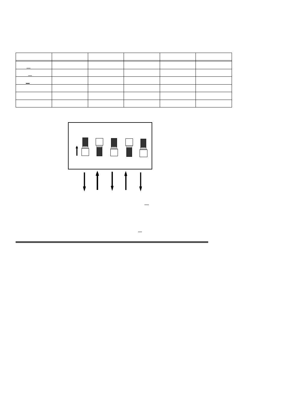
Use Switch bank S1 to select the output range of Channel 0.
Use Switch bank S2 to select the output range of Channel 1.
Table 3-2. Range Selection Switch Positions
D
D
U
D
U
0 to 2.5V
U
D
U
D
U
0 to 5V
D
U
U
D
U
0 to 10V
D
D
D
U
D
+2.5V
U
D
D
U
D
+5V
D
U
D
U
D
+10V
5
4
3
2
1
RANGE
Figure 3-3. Range Switch Block - +10V Example Shown
3.4 INSTALLING THE CIO-DAC02/16 IN THE COMPUTER
1. Turn the power off.
2. Remove the cover of your computer. Be careful not to dislodge any of the cables
installed on the boards in your computer as you slide the cover off.
3. Locate an empty expansion slot in your computer.
4. Push the board firmly down into the expansion bus connector. If it is not seated
fully it may fail to work and could short circuit the PC bus power onto a PC bus
signal. This could damage the motherboard in your PC as well as the
CIO-DAC02/16.
4
O
N
Range switches set for +10V
1
2
3
4
5
- ACC-300 (7 pages)
- AI-EXP32 (20 pages)
- AI-EXP48 (19 pages)
- BTH-1208LS (30 pages)
- 6K-ERB08 (32 pages)
- BTH-1208LS Quick Start (4 pages)
- 6K-SSR-RACK08 (33 pages)
- BTH-1208LS-OEM (27 pages)
- CB-COM-Digital (68 pages)
- CB-7018 (68 pages)
- CB-7000 Utilities (44 pages)
- CB-7080D (74 pages)
- CB-COM-7033 (44 pages)
- CB-COM-7017 (72 pages)
- CB-COM-7024 (76 pages)
- CB-NAP-7000P (36 pages)
- CIO-DAC02 (18 pages)
- CB-NAP-7000D (56 pages)
- CIO-DAC16-I (16 pages)
- CIO-DAC16/16 (20 pages)
- CIO-DAS08 (21 pages)
- CIO-DAC16 (20 pages)
- CIO-DAS08/JR (16 pages)
- CIO-DAS08/JR/16 (14 pages)
- CIO-DAS08/JR-AO (16 pages)
- CIO-DAS08-AOM (32 pages)
- CIO-DAS08-PGM (28 pages)
- CIO-DAS16/330 (34 pages)
- CIO-DAS48-I (17 pages)
- CIO-DAS16/M1 (38 pages)
- CIO-DAS48-PGA (18 pages)
- CIO-DAS800 (20 pages)
- CIO-DAS802/16 (22 pages)
- CIO-DAS6402/16 (40 pages)
- CIO-DAS-TEMP (20 pages)
- CIO-DDA06/16 (18 pages)
- CIO-DDA06/JR (17 pages)
- CIO-DIO24/CTR3 (21 pages)
- CIO-DIO24H (20 pages)
- CIO-DI192 (24 pages)
- CIO-DDA06 (21 pages)
- CIO-DIO48 (19 pages)
- CIO-DO192H (16 pages)
- CIO-DIO192 (20 pages)