5 data registers – Measurement Computing CIO-DAC02/16 User Manual
Page 10
5 DATA REGISTERS
The CIO-DAC02/16 has four analog-output data registers. There are two for each
channel, one for the lower eight bits and one for the upper eight bits. The first address
(BASE ADDRESS) is determined by setting a bank of DIP switches on the board.
The information presented in this chapter is intended for experienced programmers. If
you are not familiar with register manipulation, we encourage you to use the Universal
Library.
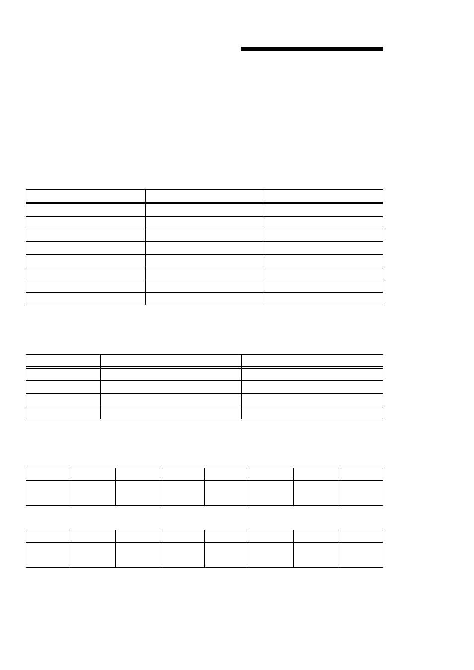
To write to or read from a register in decimal or HEX, the following weights apply:
80
128
7
40
64
6
20
32
5
10
16
4
8
8
3
4
4
2
2
2
1
1
1
0
HEX VALUE
DECIMAL VALUE
BIT POSITION
The registers and their function are listed on Table 5-1.
Table 5-1. Data Registers
Initiate simultaneous update.
D/A 1 Most Significant Byte
BASE + 3
Initiate simultaneous update.
D/A 1 Least Significant Byte
BASE + 2
Initiate simultaneous update.
D/A 0 Most Significant Byte
BASE + 1
Initiate simultaneous update.
D/A 0 Least Significant Byte
BASE + 0
READ FUNCTION
WRITE FUNCTION
ADDRESS
The bits of the registers are labeled as follows:
BASE + 0 and BASE +2 (LEAST SIGNIFICANT BYTE)
DA16
(LSB)
DA15
DA14
DA13
DA12
DA11
DA10
DA9
0
1
2
3
4
5
6
7
BASE + 1 and BASE +3 (MOST SIGNIFICANT BYTE)
DA8
DA7
DA6
DA5
DA4
DA3
DA2
DA1
(MSB)
0
1
2
3
4
5
6
7
6