Mathey Dearman Saddle Machine Contour Cutting Attachment User Manual
Page 6
6
8.1 – MSA
-
Remove the 2 bottom Hex Head Cap Screws (A) from the cap ring (the part that holds the rotating ring gear to the saddle
assembly). Place the holes in flanges of the template over the holes in the cap ring, where the screws are designated to be
removed and reinstall the hex head screws.
8.2 – 1SA
-
Remove the 2 bottom (A) and the top (D) center Hex Head Cap Screws from the cap ring (part which holds the rotating
ring gear to the saddle). Place the holes in the flanges of the template over holes in the cap ring, where the screws were
removed and reinstall the Hex Head Cap Screws.
8.3 – 2SA
-
Remove the 2 upper (C) and 2 lower (A) Hex Head Cap Screws from the cap ring (part which holds the rotating gear to the
saddle). Place the holes in flanges of the template over holes in the cap ring, where the screws were removed and reinstall
the hex screws.
8.4 – Super “ II”-
Remove the 2 upper (C) and the 2 lower (A) center Hex Head Cap Screws from the cap ring (part which holds the rotating
gear to saddle). Place the holes in flanges of the template over holes in the cap ring, where the screws were removed and reinstall
the hex head screws.
8.5 – 3SA -
Remove the 2 bottom (A) and the top (D) center Hex Head Cap Screws from the cap ring (the part that holds the rotating gear to
saddle). Place the holes in flanges of the template over the holes in the cap ring, where the screws were designated to be removed
and reinstall the hex head screws.
8.6 – 4SA
-
Remove the 2 upper (C) and the 2 lower (A) Hex Head Cap Screws from the cap ring (the part which holds the rotating gear to
saddle). Place the holes in flanges of the template over the holes in the cap ring, where the screws were designated to be removed
and reinstall the hex head screws.
8.7 – 5SA
-
Remove the 2 upper (C) and the 2 lower (A) Hex Head Cap Screws from the cap ring (part which hold the rotating gear to saddle).
Place the holes in flanges of the template over holes in the cap ring, where the screws were removed and reinstall the hex head
screws.
8.8 - 6SA
–
Remove the 2 upper (C) and the 2 lower (A) Hex Head Cap Screws from the cap ring (the part that holds the rotating gear to
saddle). Place the holes in flanges of the template over holes in the cap ring, where the screws were designated to be removed and
reinstall the hex head screws.
8.9 – 8SA
–
Remove the 2 upper (C) and the 2 lower (A) Hex Head Cap Screws from the cap ring (the part that holds the rotating gear to
saddle). Place the holes in flanges of the template over holes in the cap ring, where the screws were designated to be removed and
reinstall the hex head screws.
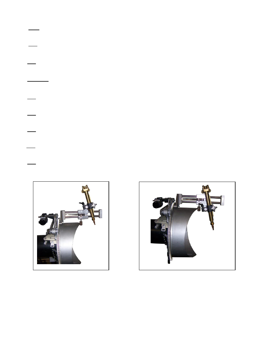
There is no longer a need for a 18” long machine torch when cutting the smaller
diameters that the machine will cut. To facilitate a 12” machine torch for all diameters,
the Torch Carriage Assembly now has torch bracket mounting holes at the top and
bottom of the assembly.