Operating instructions - clamping cylinders – Kreg KFT4X8 Face-Framing Table User Manual
Page 7
R
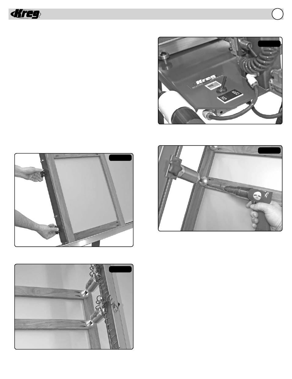
Clamping Cylinders
Each of the four clamping cylinders included with this framing table
throw over 400 lbs. per square inch of pressure on the joint line. Each
clamping cylinder can be moved independently of every other cylinder
by simply sliding it up and down the transfer arm. A toggle switch is
located on the top of each cylinder assembly that controls air fl ow
to that particular cylinder. Each cylinder can then be turned on or off
independently of the other cylinders. In addition, a master switch is
located at the bottom of the transfer arm that has the ability to control
all of the cylinders at one time (if they are in the “on” position).
To Clamp and Join a Frame:
1) Place workpiece into alignment with squaring fence
2) Adjust clamp pad so that it is directly over the joint line
3) Throw cylinders independently or all at once with the master switch
4) Drive screws and repeat process
ing
Figure 1
Figure 2
Figure 3
Figure 4
Place workpiece into alignment with squaring fence
Adjust clamp pad so that it is directly over the joint line
Throw cylinders independently or all at once with the master switch
Drive screws and repeat process
Operating Instructions - Clamping Cylinders
6.