Kemppi Evo 170 User Manual
Page 15
EN
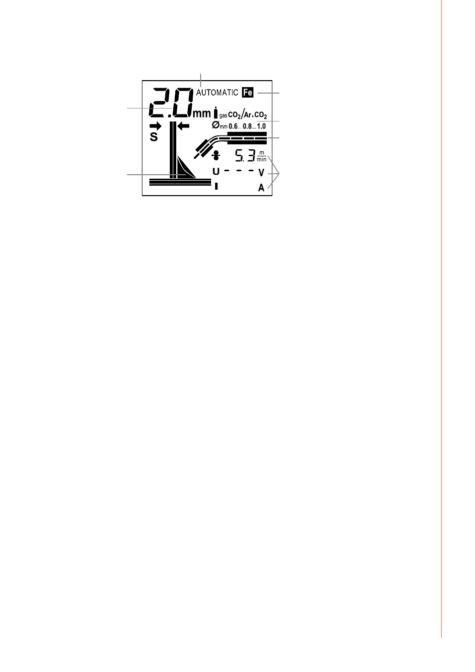
2.8.1 Display in automatic mode
1.
2.
4.
5.
7.
6.
3.
Machine display in automatic mode
1.
Material thickness
2.
Visual material thickness and weld shape indicator
3.
Operating mode reference
4.
Material selection
5.
Shielding gas and wire diameter recommendation
6.
Wire feed graphic
7.
Welding values: Wire feed speed, welding voltage and welding current
MinarcMig Evo 200 automatically sets the machine based on your input selections for plate
thickness in mm, weld shape and material type. The material thickness graphic display shows
the selected plate thickness to be welded. Your machine is automatically set for welding
following these parameters inputs.
As you make your selections you will see the displayed parameters change. For example,
as you adjust the power/plate thickness control, you will see the graphic indicating plate
thickness become thicker or thinner.
The selected operating mode and material type are also shown on the display. The display
also shows a recommendation for shielding gas and filler wire diameter for the material in
question. During welding, the graphical display shows that wire feeding is active including
the wire feed rate. Of all the welding parameters, only filler wire feed speed is visible on the
display all the time. Welding voltage and welding current are only visible on the display during
welding. The last used values remain on the display until welding is restarted or parameter
settings are changed.
When adjusting the arc length, weld shape, or voltage control, the voltage display shows
a comparative scale (-9…0…9) which will disappear from the display after a preset time
following adjustment.
2.8.2 Welding power adjustment in automatic mode
Adjusting the welding power according to sheet thickness affects simultaneously both wire
feed speed and amount of current delivered to the filler wire. This is a good starting point
for welding in different operating situations. However, welding joint type and root opening
may influence the amount of welding power required. Select the correct welding power
using the power control, whilst viewing the graphical display of the fillet weld and sheet
thickness indicator. If the fillet weld’s sheets are of different thickness, use their average as a
default parameter and test weld. The sheet thickness display is given in millimetres and with
steel and stainless steel wires, is based on 0.8 mm filler wire diameter. When using a 0.6 mm
filler wire, set the welding power control slightly higher than the used sheet thickness and
correspondingly slightly lower with 0.9–1.0 mm wires. With aluminium wires, the welding
power adjustment is based on 1.0 mm wire diameter.
13
© Kemppi Oy / 1340