8 controls and indicator lights – Kemppi Evo 170 User Manual
Page 13
EN
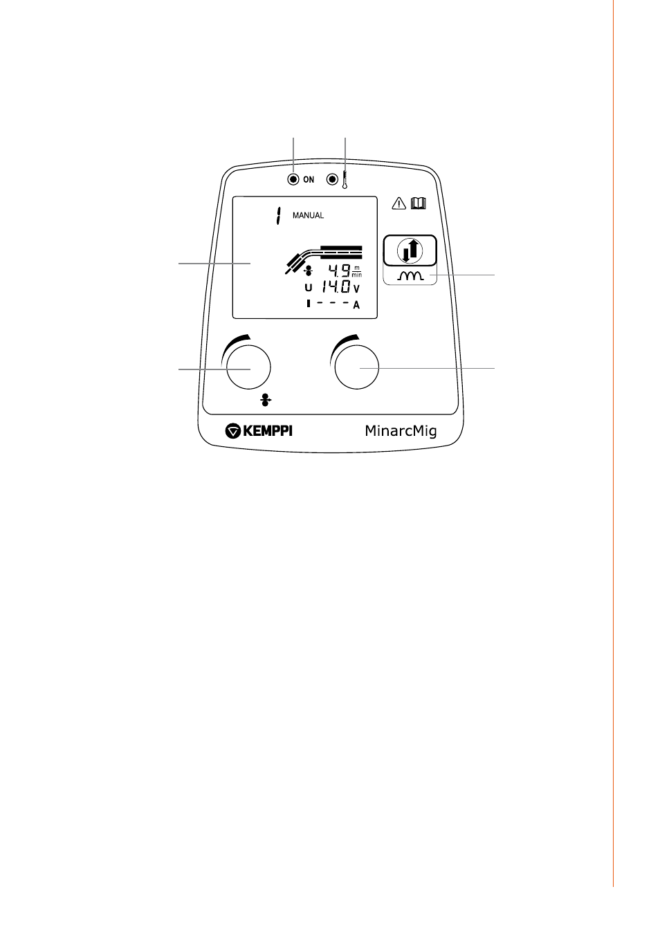
2.8 Controls and indicator lights
minarcmig evo 170 control panel
U
W006095
1.
2.
3.
4.
5.
6.
1.
Wire feed speed control
2.
Welding voltage control
3.
Dynamics selection control
4.
Standby indicator light
5.
Overheating indicator light
6.
Display
Wire feed speed and welding voltage values are set and adjusted independently. Guide
parameter values can be viewed on page 15 of this manual.
The Dynamics selection control offers a choice of two settings and controls the rate of rise
of current during the welding process, when the filler wire is in contact with the weld piece.
Use Dynamics setting 'I' for lower welding parameter settings and small filler wires, and 'II' for
higher parameter settings and larger filler wires.
Indicator lights display the machine’s standby mode and inform of a possible welding duty
cycle temperature limit. When you switch the machine on, a green standby light switches on.
Simultaneously, the main switch indicator light switches on. If the machine reaches its duty
cycle limit during welding or the supply voltage is too low or too high, the welding operation
automatically switches off and the yellow overheating indicator light switches on. The light
switches off when the machine has cooled and is ready for operation again. Make sure that
there is enough space around the machine to allow fresh air to freely circulate and cool the
machine.
NOTE!
Always start and stop the machine from the main switch, never use the plug as a switch!
11
© Kemppi Oy / 1340