JLCooper MLA-1 User Manual
Page 8
MLA-1 / MLA-10
Installation/Operations Manual
8
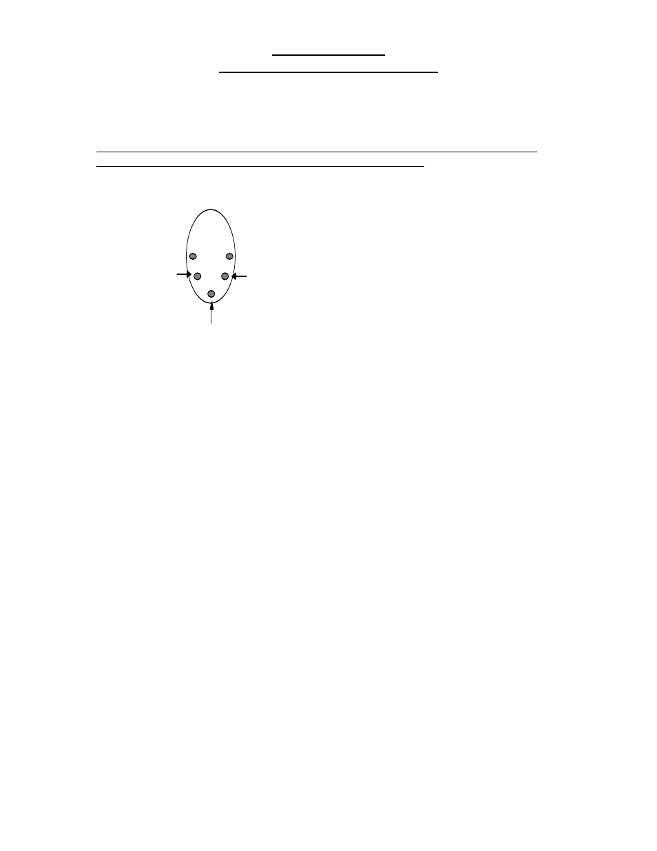
Please note that a 5-pin DIN connector is not numbered with consecutive pin
numbers. Viewed from the rear, the pin-out for the DIN is:
Pin 2
Pin 4
Pin 5
Rear View, DIN Ja
Special Interest notes:
1.
One output may be connected to as many as 4 inputs. For instance, pins
1 &2 of a MLA-10 could be attached to pins 9 &10 of up to 4 other MLA-10's. The
opposite of this is not true!!
For instance, pins 1 & 2 of multiple units may not
be attached to pins 9 &10 of another. This would result in outputs fighting each
other.
2.
While this multiple-slave approach may be used with MLA-1's also, it is not
possible to remotely power multiple MLA-1's from one MLA-10's. If Multiple
MLA-1's are to be used, contact the factory for instructions about modifying the
MLA-1's for local power.
3.
When working with an MLA-1, you will be constructing some number of
panels with MIDI Jacks. You should keep in mind that, according to the MIDI
specification, the MIDI Input jacks have no ground connection. Only pins 4 and 5
need be connected, pin 2 is left unconnected. The MIDI Output jacks, however,
have pin 2 going to ground. If you are trying to find a source for 5-pin DIN jacks,
we recommend Switchcraft part number 57GB5F. These can be mounted with
screws or rivets.