Mla-10, Mla-1 / mla-10 installation/operations manual – JLCooper MLA-1 User Manual
Page 4
MLA-1 / MLA-10
Installation/Operations Manual
MLA-10
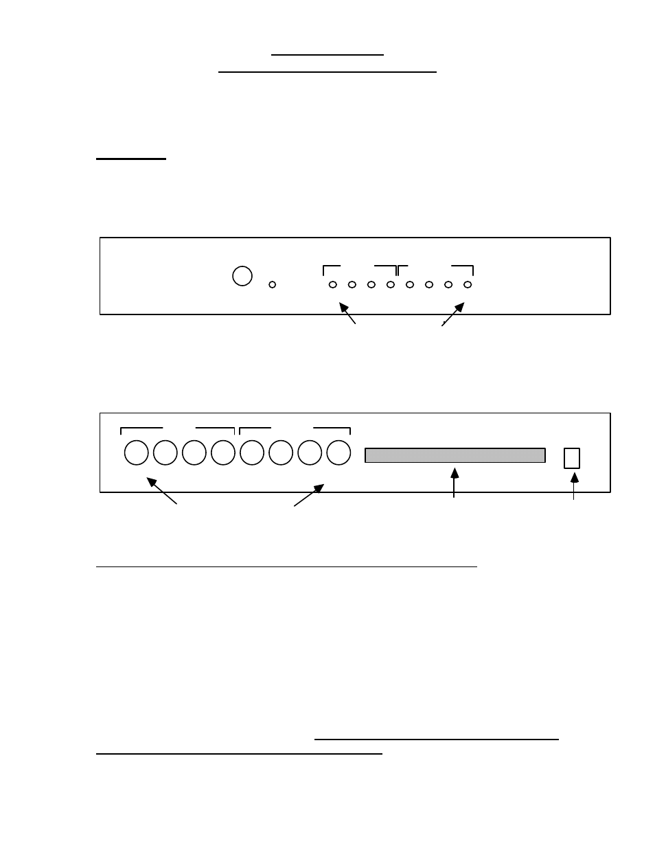
The front panel of the MLA-10 has the Power switch and LED and the MIDI
activity LEDs. These activity LEDs will flicker whenever the associated channel
carries MIDI data.
Power
INPUT
OUTPUT
1
2
3
4
1
2
3
4
Activity LEDs
The rear panel of the MLA-10 has the power connector for the wall transformer,
the eight MIDI connectors, and the terminal strip for the multi-pair long run cable.
1
24
INPUT
OUTPUT
1
3
4
2
1
3
4
2
Power
9VDC
Midi Connectors
Long run Multi-pair cable
The definition of the pins of the terminal strip are as follows:
Pin
Name
Pin
Name
Pin
Name
1
MIDI In #1 (-)
9
MIDI Out #1 (-)
17
Ground
2
MIDI In #1 (+)
10
MIDI Out #1 (+)
18
Ground
3
MIDI In #2 (-)
11
MIDI Out #2 (-)
19
Ground
4
MIDI In #2 (+)
12
MIDI Out #2 (+)
20
Ground
5
MIDI In #3 (-)
13
MIDI Out #3 (-)
21
+9 VDC
6
MIDI In #3 (+)
14
MIDI Out #3 (+)
22
+9 VDC
7
MIDI In #4 (-)
15
MIDI Out #4 (-)
23
+9 VDC
8
MIDI In #4 (+)
16
MIDI Out #4 (+)
24
+9 VDC
This means that a MIDI signal put into the MLA-10's MIDI Input #1 will be
converted and transmitted out on pins 1 and 2 as a ± pair. Pins 17 thru 24 are
intended as output power to a MLA-1. Under no circumstances should pins 21
thru 24 be attached between two MLA-10 units.
4