Mla-1 – JLCooper MLA-1 User Manual
Page 6
MLA-1 / MLA-10
Installation/Operations Manual
MLA-1
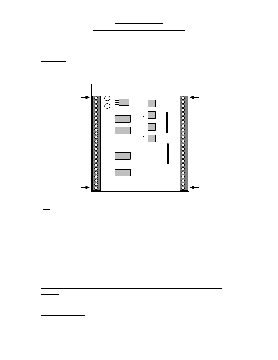
With the cover removed, this PC board is found:
J1
J2
Pin 1
Pin 1
Pin 24
Pin 24
To
Multi-pair
long cable
To
Midi DIN
Connectors
Note that pin 1's are closest to P
C board edge
J1
This connector will attach to the long multi-twisted-pair cable. For each MIDI
channel used, a cable pair is needed. In addition, at least two pair of wires are
needed for power if the MLA-1 is being powered remotely from a MLA-10. If more
conductors are available, they should also be used for power. This will minimize
the voltage drop thru the cable.
When attaching a MLA-1 to a MLA-10, wiring is very simple: Pin 1 on the MLA-1
goes to Pin 1 on the MLA-10 and so forth until pin 24.
If only 10 pair cable is used, skip past pins 19 and 20 on both ends. This
will provide two conductors of ground and two conductors of +9 VDC
power.
We strongly recommend that a minimum of 22 AWG twisted pair
cable be used.
An example of this would be Belden #9747, which is non-
shielded 12 pair.
6