ikan V17 User Manual
Uick, Tart, Uide
INTRODUCTION
Thank you for purchasing the ikan V17 LCD Monitor. We know that you will be satisfied with our “V” series monitors.
Please visit www.ikancorp.com for more information on our current and future products including our award-winning
fluorescent studio lights and light accessories.
PACKAGE INCLUDES
V17 LCD Monitor
AC Power Adapter
GETTING STARTED
1. Powering The Monitor. To do this, you have two options.
a) You can plug the AC power cord into the power input jack located on the right side of the rear of the monitor.
b) You can connect a pro battery using the optional pro battery plate and then plugging that plate into the DC-In
connector. The pro battery plate kits (PBPK-S or PBPK-A) allow you to go into the field using standard V-Mount
or Gold-Mount batteries.
2. Connecting The Video Source
The V17 allows you to connect to your source feed, using any of the following connections: S-Video (Y/C),
SD/HD Component, Composite (A/V), and HDMI Inputs/Outputs.
Checked by
CONDITIONS OF WARRANTY SERVICE
• Free service for one year from the day of purchase if the problem is caused by manufacturing errors.
• The components and maintenance service fee will be charged if the warranty period has expired.
Free Service will not be Provided in the Following Situations: (
** Even if the product is still within the warranty period.)
• Damage caused by abuse or misuse, dismantling, or changes to the product not made by the company.
• Damage caused by natural disaster, abnormal voltage, and environmental factors etc.
Q
UICK
S
TART
G
UIDE /
V17 LCD MONITOR
3903 Stoney Brook Dr. Houston TX 77063. 1-713-272-8822. [email protected] © 2009 ikan Corporation. All right reserved. www.ikancorp.com
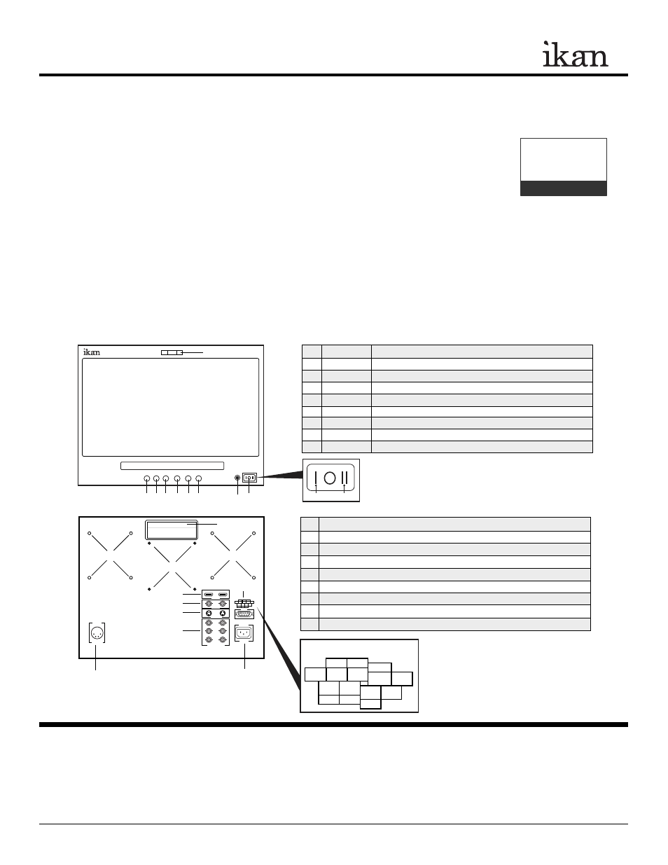
1. POWER
Power switch (I = AC On, O = Off, II = DC On)
2. LAMP
Power signal indicator
3. GUIDES
On-screen guide: 4:3 or 16:9
4. ASPECT
Aspect ratio: 4:3 or 16:9
5. INPUT
A/V (Composite), S-Video, SD/HD Component, HDMI
6. >
While in MENU mode, toggle as up adjust setting
7. MENU
Access to all monitor settings: Brightness, Hue, etc.
8. <
While in MENU mode, toggle as down adjust setting
9. LAMP
Tally Lights
MONITOR DIAGRAMS
1. AC 110V-220V Power Connection
2. DC 12V-24V Power Connection
3. HDMI Input
4. A/V - I/O for standard definition composite signal
5. S-Video - I/O for standard definition S-Video signal
6. Component - I/O for standard definition, 720p, and 1080i HD signals
7. Tally
8. Handle
9. 100mm Holes for Vesa Mount / Pro Battery Mounting Plates
V17-031909-03
1
2
3
4
5
6
7
8
9
[ Labeling Box ]
1
2
3
4
5
6
7
8
9
9
9
V17
< MENU > INPUT ASPECT GUIDE
5
9 8 7 6
4
RED GREEN
YELLOW
GND
GND
GND
3 2 1
Tally Light - Pin Configurations
AC In
DC In
Tally Light Operation
• Do not provide power to tally connections.
• Tally light system is unpowered and works by closing
the contact between any of the grounding pins and the
pin for the desired LED color.
IN OUT
VIDEO
S-VIDEO
Y
Pb
Pr
COMPONENT
HDMI
12v-24v
DC IN
110~220v
5
9 8 7 6
4
RED GREEN YELLOW
GND
GND
GND
3 2 1
TALLY
AC IN