Bypass and wdt – IBASE IB831 User Manual
Page 19
INSTALLATION
IB831 User’s Manual
15
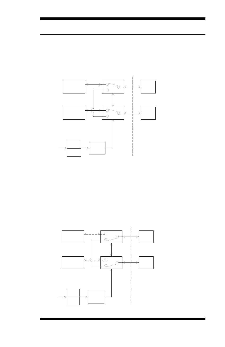
Bypass and WDT
The bypass function is used to link (or short) two independent Ethernet
ports when user’s application software halts or when power is off.
Block Diagram:
I/O Command
Relays are "Energized"
Normal State
Driver
Relay
GPIO
Ethemet#2
Ethemet#1
Bypass
RJ45
Relays
RJ45
WDT
CN11
CN12
Communication States:
There are two communications states for the bypass function: (1) Normal
State, (2) Bypass State. A watchdog timer (WDT) or a GPIO are used to
control and switch the communication between the two states.
The block diagram in the section above shows the Normal State, where
the two Ethernet ports work independently. The following diagram
shows the Bypass State, where the two Ethernet ports are bypassed.
I/O Command
Relays are "Dis-energized"
Driver
Relay
Bypass State
Ethemet#2
Ethemet#1
Bypass
RJ45
Relays
RJ45
WDT
GPIO
CN11
CN12