Hypertherm HySpeed HT2000 Plasma Arc Cutting System Rev.7 User Manual
Page 42
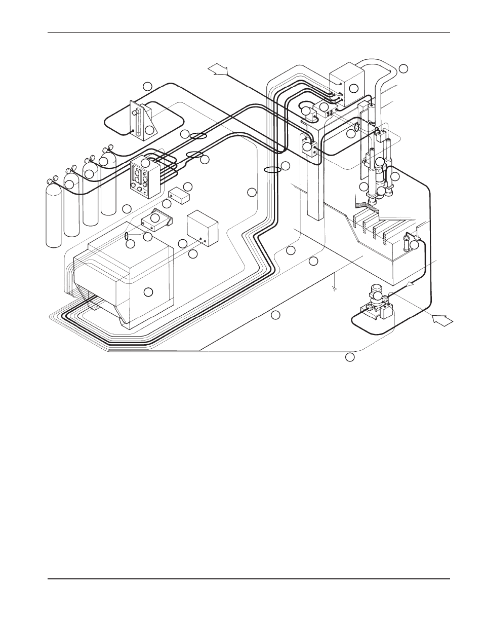
ORDERING PROCEDURE
HySpeed HT2000
Product Configuration Manual
2-23
6
1
Power Supply
2
Torch Assembly
3
Remote High Frequency Console
4
Leads Between Power Supply and Remote High Frequency Csl
5
Shielded Leads Between Torch and Remote High Frequency Csl
6
Gas Console
7
Motor Valve Console
8
Leads Between Gas Csl and Motor Valve Csl
9
Shield Gas Hose Set Between Gas Csl and RHF Csl
10
Cable Between Gas Csl and Power Supply
11
Cable Between Motor Valve Csl and Power Supply
12
Remote Voltage/Current (V/C) Control
13
Cable Between PS and Dig. Remote/Current Remote
14
Cables Between PS and Progr. Remote
15a Cable Between PS and Machine Computer I/O Interface
Figure 2-13
Final System Interconnect with Options – System Layout
7
20
22
21
21
21
5
18
18
18
18
19
11
1
2
4
25
3
13
12
15
b
15
a
20
a
6
16
15b Cable Between PS and Machine Computer V/C Interface
16
Cable Between PS and Work Table
17* Hold Cable Between Power Supplies in Multi-Torch Systems
18
Inductive IHS System/Air Regulator/Mntg Brckt
19
Inductive IHS Lead Set
20
Timer / Counter
20a Cable Between Tmr/Cntr and Power Supply
21
Water Muffler System
22
Cable Between Water Muffler Pump and Power Supply
23
Hosing Between Supply Gases and Gas Csl
24
Argon/Hydrogen Console
25
Cable Between Argon/Hydrogen Console and Power Supply
26
Hose Between Argon/Hydrogen Console and Torch
* Not Shown
Block Diagram representation on page 2-22
Power
19
9
8
24
26
23
23
23
10
Air
14