Care and maintenance - 5000 series models – Dixon ZTR 5423 User Manual
Page 33
CARE AND MAINTENANCE - 5000 SERIES MODELS
MOWER DECK INSTALLATION:
NOTE: Brake link (P/N 5283) normally used for installation of engine to mower deck
drive belt, has been placed in position during assembly of the lift frame at
the factory. For shipment purposes, the brake link has been secured with
a cotter pin and washer. REMOVE AND DISCARD cotter pin and washer
after engine to mower drive belt has been installed.
1. Loosen and remove front body mounting bolts (P/N 3368) and washers (P/N 3066).
Disconnect headlight wiring plug from wiring harness. Lift front body from chassis.
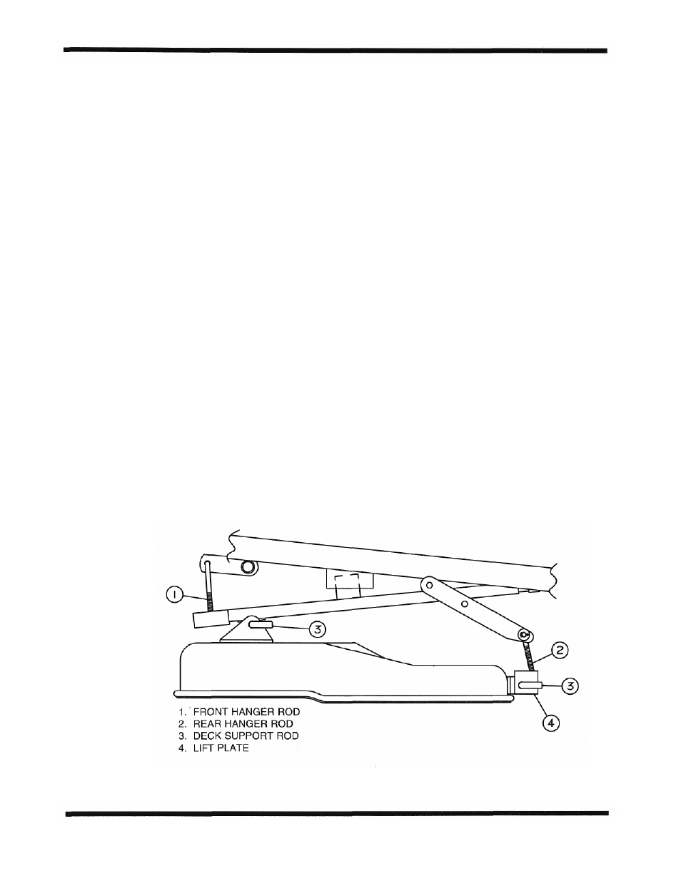
2. Install rear hanger rods on lift frame. Slide lift plate on hanger rods, small holes in
lift plate will face rear of mower, and start nylok nuts on each hanger rod until
approximately 1/2 inch of threads are exposed.
3. Position mower deck under chassis.
4. Raise front of mower deck and slide front support rod through lift frame and tabs on
mower deck. Install hair pin clips on front and rear of support rods.
5. Move lift lever to lowest cut position, install engine to mower deck drive belt on top
center pulley. Check belt routing after installation to make certain that belt is
centered in groove of electric clutch pulley.
6. Move lift lever toward high cut position and remove brake link from hole on lift lever.
7. Install front body, connect headlight wiring.
Page 30