Herrmidifier Herrtronic RDU-D User Manual
Page 6
Herrtronic
®
RDU-D Supplement
I n s t a l l a t i o n , O p e r a t i o n , & M a i n t e n a n c e M a n u a l
6
www.herrmidifier-hvac.com
V. REMOTE MOUNT OPTION (MDM, MDS, MDD)
1. The RDU may hang directly on a wall using the two
1/4” x 2” lag screws included. There are two key-hole
slots on the back of the cabinet which engage these
screws. Be certain that: 1) the screws are fastened
securely enough to the wall to support the 40 lbs.
weight of each RDU unit, and 2) the screws are level.
Turn the screws in until the heads are 1/8” away from
the mounting surface.
2. Hang the unit on the wall and tighten the two lag
screws.
3. The steam hose(s) is to be connected using the steam
inlet union(s) (Figure 8).
4. Trim the steam hose(s) which is connected to the RDU
manifold so that it fits properly onto the union(s) and
secure connections with a hose clamp(s).
5. Fasten steam inlet union(s) to bottom or back of RDU
cabinet with screws.
6. Remove the knockout from the top of the Herrtronic
cabinet and install the 5/16” I.D. plastic bushing
(included).
7. Remove the 18” piece of condensate return tubing
connected to the manifold elbow.
8. Uncoil the 10’ piece of condensate return tubing (drain
line), feed into the RDU cabinet, from the bottom or
back, and connect to the manifold elbow.
9. Run the condensate return tubing down into the
Herrtronic cabinet through the 5/16” I.D. plastic
bushing.
10. The condensate tubing can be attached to the steam
hose or electrical conduit interconnecting the RDU
and Herrtronic with cable ties or equivalent.
11. After the condensate tubing is secured, insuring that
there are no kinks or low spots, the length should be
trimmed so that it can extend 1” into the grey plastic fill
tee in the Herrtronic unit.
12. National, state or local electrical codes may require
the use of two separate conduits - one for high voltage
supply power and one for control wiring.
13. There are a total of seven wires which are to be
connected between the RDU and the Herrtronic unit.
The RDU receives all of its power and control from the
Herrtronic unit. Use the two 7/8” holes or knockouts
on the bottom or back of the RDU cabinet and the two
7/8” knockouts on the top of the Herrtronic cabinet for
wiring conduit.
14. Wires #3 and #4 are the high voltage power supply
and should be run in one conduit.
15. Along with the ground wire #24, wires #1, #2, #5, and
#6 should be run in the second conduit.
16. Connect wires # 1-6 to the 6 pole RDU terminal strip
located near the top of the Herrtronic high voltage
electrical compartment. Connect the ground wire #24
to the Herrtronic ground terminal located near the
bottom of the high voltage compartment.
NOTE
See Figure 15, 16 & 17 for standard electrical hookup
for MDM and MDS.
17. Remove jumper wire #39 from the Herrtronic 12
pole controls terminal strip located in the low voltage
electrical compartment between poles #1 and #2.
18. Replace the RDU cover and the fan speed control
knob.
Installation is now complete. Proceed to the RDU operation
section then to the start-up section of the Herrtronic
Installation, Operations and Service Manual OM-93.
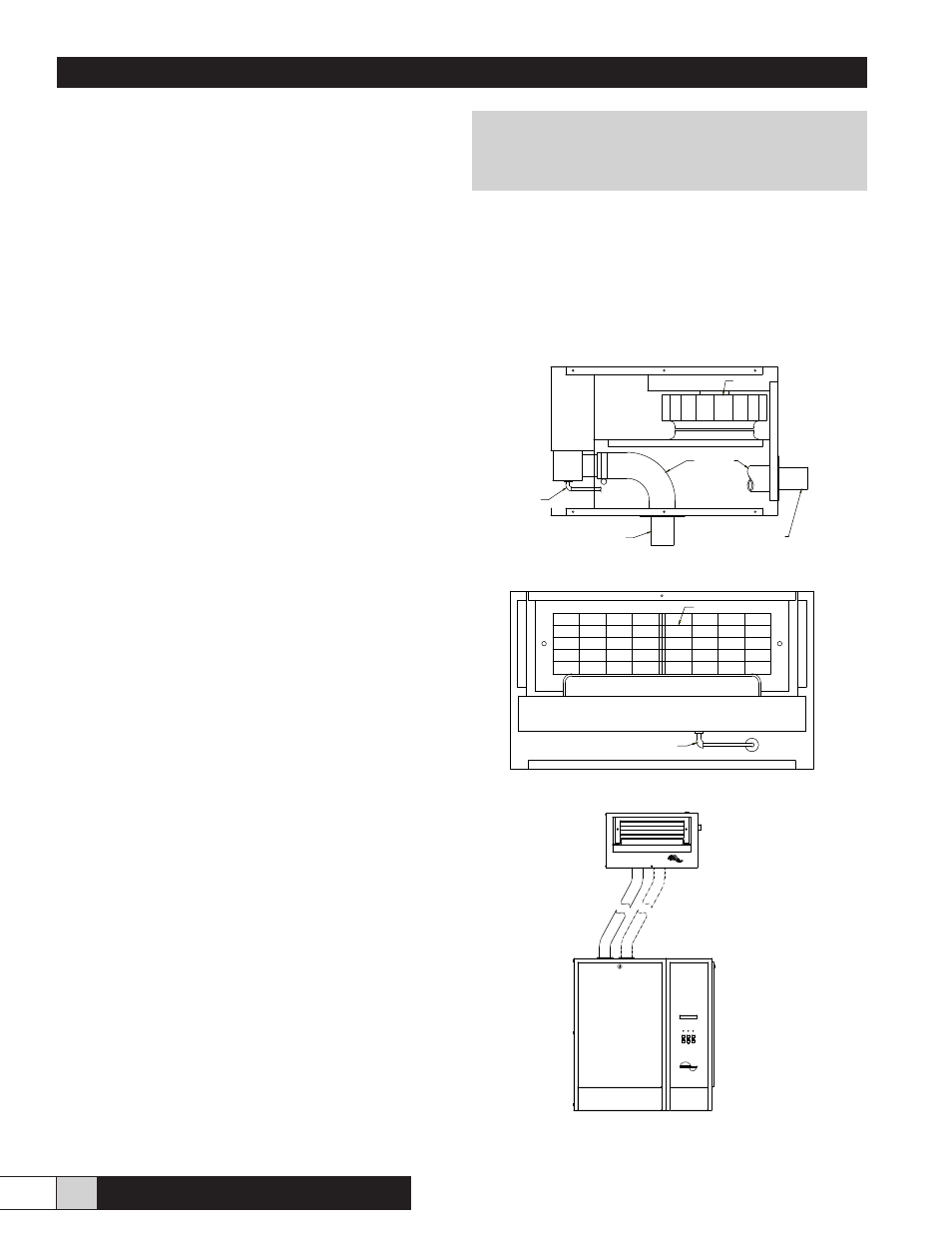
Figure 8 - Steam Connections (Side View)
Figure 9 - Drain Line (Front View)
Figure 10 - MDS Remote Mount
BLOWER
DRAIN
LINE
STEAM HOSE
STEAM INLET UNION
(REMOTE MOUNT)
STEAM INLET UNION
(ALTERNATE LOCATION)
DRAIN
LINE
GRILL
>50 lb/hr requires second hose
CYL FULL
POWER
FAULT
BACK
ON/OFF
FAULTS
ENTER
HERRTRONIC MD
Figure 10 - Front View