Gullco KBM-28 User Manual
Page 13
9
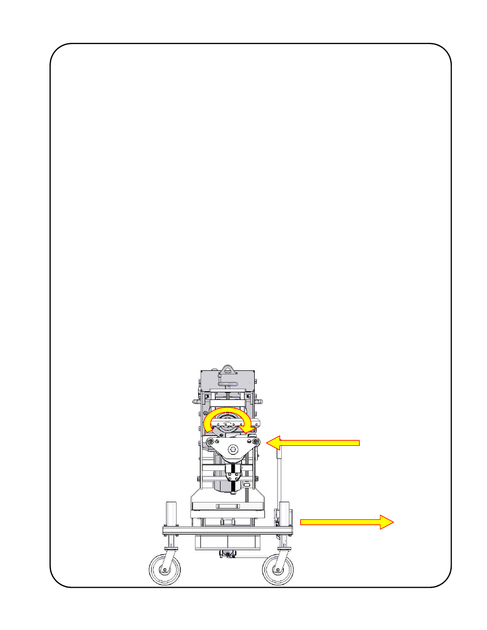
CUTTER
ROTATION
PLATE TRAVEL
MACHINE TRAVEL
As the colours of the wires in the mains lead of this equipment may not correspond with the
coloured markings identifying the terminals in your plug/receptacle, proceed as follows:
The Green wire must be connected to the terminal in the plug which is
allocated for “Earth” / “Ground”.
The Black, Red and White wires must be connected to individual terminals in
the plug which are allocated for; “Live 1” (“L1”); “Live 2” (“L2”); and “Live 3”
(“L3”). Before feeding any material into the beveller, check the cutter rotation
as described below, and swap two of these wire terminations at the plug if the
rotation is incorrect.
Note: The mechanical starter is equipped with a low voltage protection device which de-latches
(resets) the Start button whenever the voltage to the machine falls below an acceptable
level. This protects against the machine from accidentally starting up when power is re-
applied.
Note: The Emergency stop push button latches when activated and requires a counter-clockwise
twist to release.
WARNING!
As shown in the accompanying drawing, the cutter rotation MUST be clockwise (as
viewed from the front) when the direction selector switch is set to forward (“FOR”).
IT IS IMPORTANT THAT THIS ROTATION DIRECTION BE CORRECT
OTHERWISE DAMAGE TO THE MACHINE MAY OCCUR AND WARRANTY WILL
BE VOID. Be certain to check the cutter rotation before operating the machine. The
plate should be fed in the direction shown if the machine is static and the material is
being manually fed, alternatively, the bevelling machine should travel in the direction
shown if the plate is static and the machine is running along the plate. If the cutter
rotation is incorrect, it means that the 3 phase AC connection is incorrect and two out
of the three Live wires must be swapped. The correct cutter rotation direction is
shown on the clamp roller block.