Operation – Gullco GP-200 User Manual
Page 6
4
OPERATION
Note: The electrical and mechanical installation of the positioner is explained in the Technical
Manual.
Through the use of the optical tachometer closed loop feedback circuitry, the motor control can
obtain constant speed control of the welding positioner. The motor and the control operate on 24
VDC, supplied by a power supply located in the base of the positioner tower. Therefore, all
operator interface devices (except the power on/off switch) are subjected to signal level voltages
only.
Local Control Devices
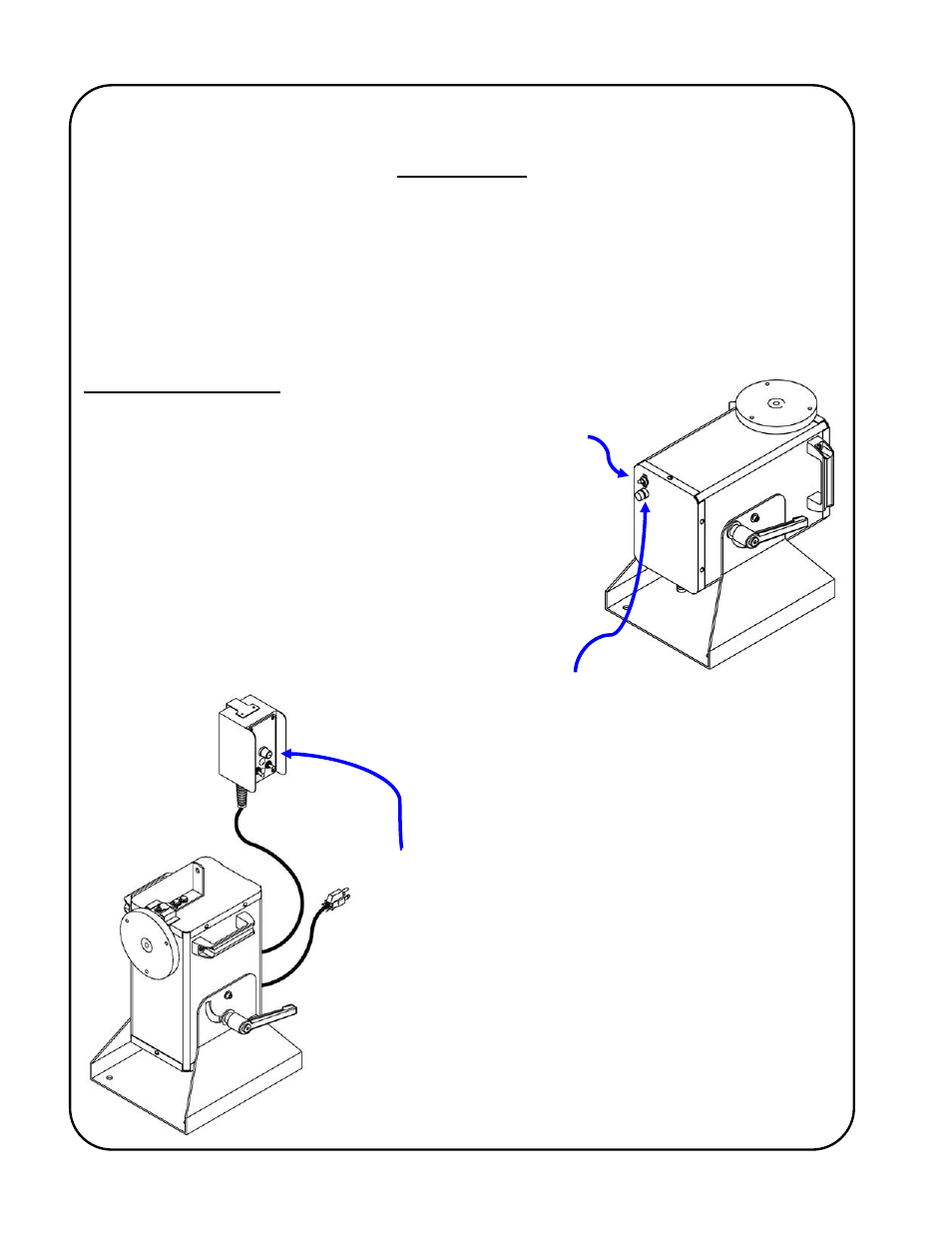
The power On/Off switch is located at the bottom of the positioner
tower and is used to disconnect the power to the rest of the
control circuitry.
I = On, O = Off.
WARNING!
The motor control must not be continually started
and stopped by the removal and reapplying of
power to the control. Turning the power off to the
control will not provide instant braking and
continued use will damage the control. Allow ten
(10) seconds after the removal of power before
reapplying the power to the motor control.
The fuse holder is located at the bottom of the positioner
tower and allows accessibility to the main AC fuse by pushing
the cap in towards the main body and twisting in a counter-
clockwise direction.
The GP-200, GPP-200 & GP-300 welding positioners use a
Gullco GSP-1000 microprocessor based motor control,
located in a remote pendant attached to the positioner by 6ft
[1.8 Mtrs] of control cable.