Groth 8391B User Manual
Page 7
6
electrode with care because the internal ceramic insulators can be easily damaged. When replacing, make
sure the electrode housing is approximately 1/10” below the deflector angle at the top of the burner.
After the inspection has been completed, power and pilot gas should be restored to the unit. Then check
the following operational items:
1. Turn the selector switch to the "MANUAL" position.
2. You should be able to hear the electrode arcing at the top of the pilot gas assembly. This should
continue for 10 seconds. If no flame is established there will be a 3 second delay before the electrode
will repeat the ignition part of the cycle. When the pilot is ignited, turn the selector switch to the "OFF"
position. All panel lamps have a “Push-to-test” feature to verify that the bulbs are functional. Refer to
Table 2.
TABLE 2
LAMP INDICATOR
LAMP COLOR
INDICATOR
Green
T/C Monitor OK
Green
Pilot Flame ON
Yellow
Pilot Gas On
Red
Pilot Flame
Failure
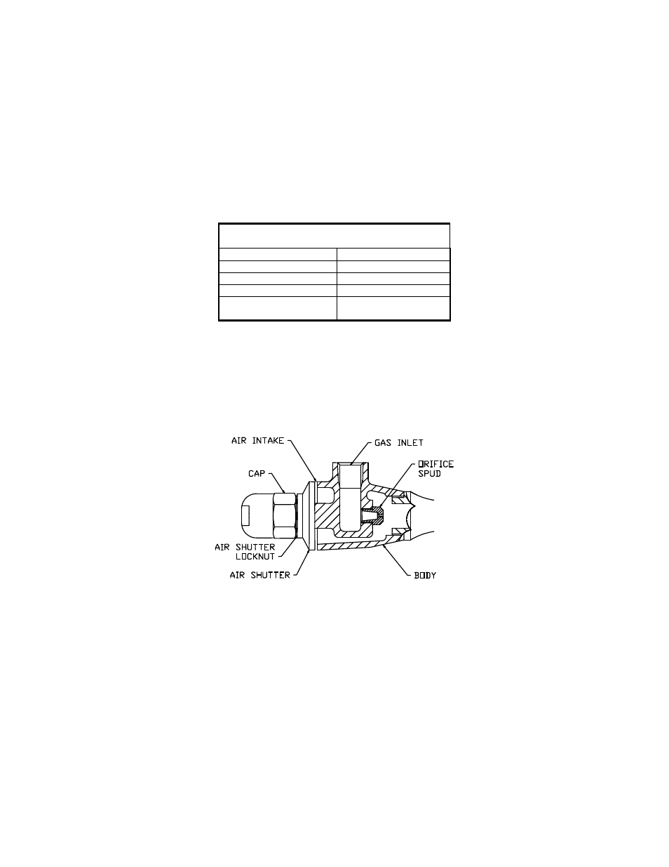
PILOT FUEL SYSTEM
1. Shut off the supply of gas to the pilot line and lock-out.
2. Disconnect fuel supply to air injector at "Gas Inlet", Fig. 1.
3. Remove air injector body at "Mixture Outlet".
4. Inspect "Orifice Spud". Diameter may vary from 0.03" to 0.13" depending on fuel pressure. Clean with
small wire or compressed air if necessary.
Figure 1 - Air Injection Assembly
5. Blow compressed air into bottom of pilot burner pipe to remove any foreign material from pipe or nozzle.
6. Replace air injector body and fuel supply connection.
7. Before lighting pilot, apply pressure and test all fuel supply connections with a soap solution.
PILOT FLAME SENSOR
1. Open the control panel cover and observe the digital display on the Omron temperature controller. The
thermocouple temperature should be displayed in the upper right corner of the screen. If the pilot is not
burning, it should display approximately ambient temperature. The upper switch point temperature setting
should be displayed in the lower right corner.
2. Relay switch status is displayed in the upper left corner. A display [ALM1 or ALM2] indicates the switch is
activated. Both switches are NO so a display means the contacts are closed. ALM1 should be displayed at
anytime the power is on. ALM2 should be displayed if the temperature [upper right] is equal to or greater
than the set temperature [lower right].