Groth 2100 User Manual
Page 6
5
Measure the distance from the top of the
pressure upper spring button [4] and the top of
the adjustment screw [6]. This should also be
recorded. Remove the top hex nut [5] from each
adjustment screw and then back off the lower
nut [5], releasing spring compression. Use care
as the nut is removed from the adjustment
screw in case of spring pre-load. Loosen the
lower nuts [11] and remove the adjustment
screws [6]. Lift the springs [3] from the valve;
handle carefully to avoid bending them or
scratching the wire.
Lift the cover (using appropriate equipment) with
one of the lifting lugs [8] and turn it upside down,
exposing the cover seal [7]. Inspect the O-Ring
for signs of mechanical damage or deterioration
from product exposure and replace if necessary.
ASSEMBLY:
This valve is built with an integral body seat. If
construction is C.S., a 316 SS weld overlay was
used to build up the seat. Consult the factory
before machining this surface.
To install a new pressure O-Ring, the cover
should be turned upside down to provide access
to the groove. It must be cleaned and can be
lubricated with a small amount of grease. The
O-Ring should be started at three or four points
around the circumference to minimize the effect
of -O-Ring stretch. Use your finger or a smooth
tool to roll the O-Ring into the groove.
Using all four lifting lugs [8], carefully lift the
cover assembly onto the body [1]. Align the
adjustment screw holes in the cover with the
body. (Depending on size and set pressure
range there are either four or eight holes.)
Place an adjustment screw [6] into each of these
holes and lock into place using the two 3/4”-10
UNC hex nuts [11] and lock washers [10]. Slide
spring buttons [4] over each of the adjustment
screws [6] and then the springs [3]. Put a spring
button [4] on top and then tighten the two 1”-8
UNC hex nuts [5] until the desired spring
compression is achieved. [Refer to the
dimension that was recorded before the valve
was disassembled.]
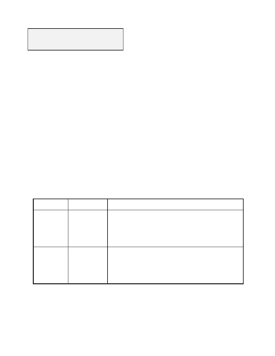
TABLE 3: TROUBLESHOOTING GUIDE
PROBLEM
INSPECTION
SUGGESTED CORRECTIVE ACTION
Vapor leakage
between the
cover & valve
top flange
Visual, audible or
vapor detector
Leakage can occur at the cover O-Ring seal and valve body seat.
This will generally occur because of deterioration of the O-Ring,
but can also be caused by mounting the valve on a warped
flange. The seat can be distorted resulting in a leak path; the
tank nozzle must be machined or replaced to correct this
condition.
Vapor leakage
between the
valve body
and tank
nozzle
Visual, audible or
vapor detector
Leakage between the flanges may be corrected by tightening the
fasteners. Follow installation instructions listed on pages 3 - 4.
The gasket may have deteriorated due to the chemical
environment; replace if required. The tank nozzle may be
warped, corroded or scratched. This will require resurfacing of
the flange face.
WARNING: Before disassembling a valve,
carefully read and understand the Safety
Warnings listed on page 3.