Groth 2100 User Manual
Page 3
2
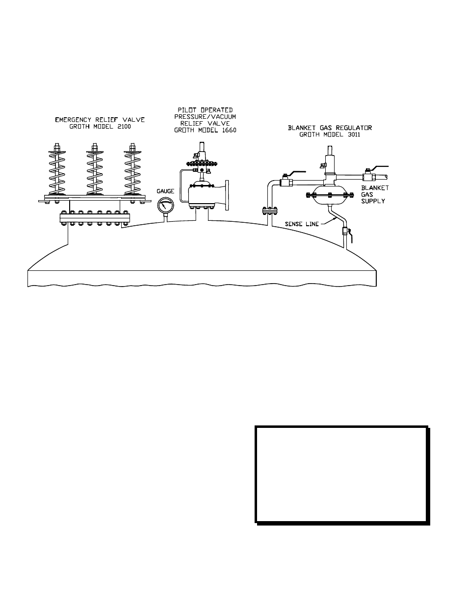
FIGURE 1: TANK INSTALLATION - SAFETY EQUIPMENT
EMERGENCY RELIEF VALVE DESIGN
AND FUNCTION
The 2100 Series Emergency Relief Valve is
designed to provide pressure relief for API 620
and 650 tanks.
This series of valve is available with a standard
O-Ring seat. Depending on application, it is
available in a wide range of material options.
Each application must be reviewed to ensure
material compatibility of all metal and soft good
components. Consult factory for special
requirements. (See Table 7 for a complete
standard material list.)
The Emergency Relief Valve is set at the factory
to comply with the specification on the purchase
order. The range of adjustment (for pressure
relief) is shown in Table 6. The pressure setting
may be changed within the design range in a
service shop.
This manual is intended to provide
recommended procedures and practices for
installation, operation, and maintenance of the
Groth 2100 Emergency Relief Valve. Any
standard procedures and practices developed
for a specific plant or process may supersede
this manual. Although this manual cannot cover
all possible contingencies, following these
guidelines should provide safe, reliable valve
performance.
For information not contained in this manual,
please contact:
Groth Corporation
A Continental Disc Company
13650 North Promenade Blvd.
Stafford, TX 77477
281-295-6800 [phone]
281-295-6999 [fax]