Groth 2100 User Manual
Page 5
4
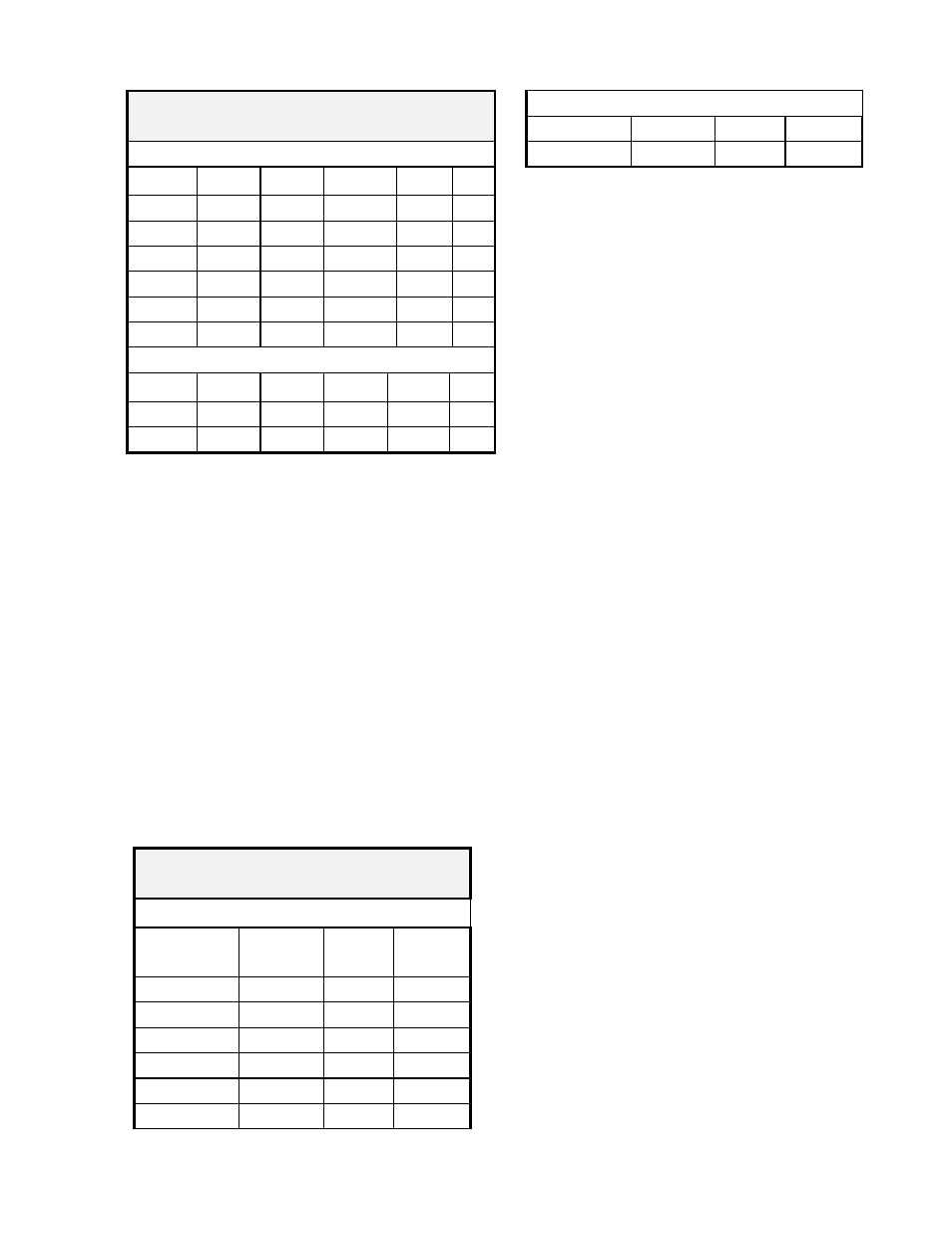
Table 1
Body Flange Gasket Dimensions
150# ANSI Flange
Size OD ID BC Hole
No.
16" FF
23.50" 15.25"
21.25"
1.13"
16
20" FF
27.50" 19.25"
25.00"
1.25"
20
24” FF
32.00" 23.25"
29.50"
1.38"
20
16" RF
18.50" 15.25"
---
---
---
20" RF
23.00" 19.25"
---
---
---
24” RF
27.25" 23.25"
---
---
---
API 650# Flange
Size OD ID BC Hole
No.
20" 26.00"
19.25"
23.50"
0.75" 16
24” 30.00"
23.25"
27.50"
0.75" 20
5. Set the valve carefully on the nozzle
6. Lubricate all studs and nuts with an
appropriate thread lubricant. If stainless
steel fasteners are used, use an anti-seize
lubricant such as moly-disulfide.
7. Install the studs in the valve body and
tighten nuts hand tight.
8. Torque all fasteners to half the value listed
in Table 2 in a staggered, alternating pattern
or follow appropriate Plant Maintenance
guideline standards.
9. Make sure that the flanges are not distorted
and that the gasket is evenly compressed.
10. Make up the final torque and check that no
further nut rotation occurs at the specified
torque value.
Table 2
Flange Bolt Torque [Ft. Lb.]
150# ANSI Flange (30 PSI MAWP)
ANSI
Flange
Number
of Studs
Stud
Size
Torque
16" FF
16
1.00”
330
20" FF
20
1.13”
410
24” FF
20
1.25”
630
16" RF
16
1.00”
225
20" RF
20
1.13”
320
24” RF
20
1.25”
500
API 650# Flange (2 PSIG MAWP)
20" 16
0.63"
22
24” 20
0.63"
25
ROUTINE MAINTENANCE
The 2100 ERV does not require routine
lubrication or adjustments. It should be checked
periodically, at least once a year, to confirm that
the valve is functioning properly and that the set
point is correct.
Periodic inspection for seat tightness should be
done to ensure compliance with local air
pollution control requirements. This may be
accomplished with a gas detector calibrated for
the principle product in the system.
The valve will need to be periodically removed
from the tank for inspection of the main cover
seal. When this is done, the valve must be
carefully lifted using the lifting eyes on the body
upper flange.
Refer to handling instructions listed in the
Installation section of this manual.
If a vapor leak is detected, it will be from one of
the following sources:
1. Cover
Seal.
2. Body - nozzle flange joint gasket.
Refer to the Troubleshooting section (p. 6) of
this manual for probable causes for these type
of problems.
TOOLS
Most service, adjustment and assembly of the
2100 valve may be performed with the following
open end wrench sizes:
15/16”, 1-1/8”, 1-1/2", 1-11/16” & 1-7/8”
DISASSEMBLY
Note that throughout this manual, numbers in [ ]
after the part descriptions are item numbers
which refer to the drawings and bills of material.
They apply only to drawing C-91726 [on page 7].
The valve should be handled by the lifting eyes
attached to the main valve body upper flange. It
should be set on a flat surface.