Two speed, Troubleshooting - two speed, Two speed assembly – Greenheck Vari-Green Motor (IOM 473681) User Manual
Page 8
8
Vari-Green Motor and Controls
Two Speed
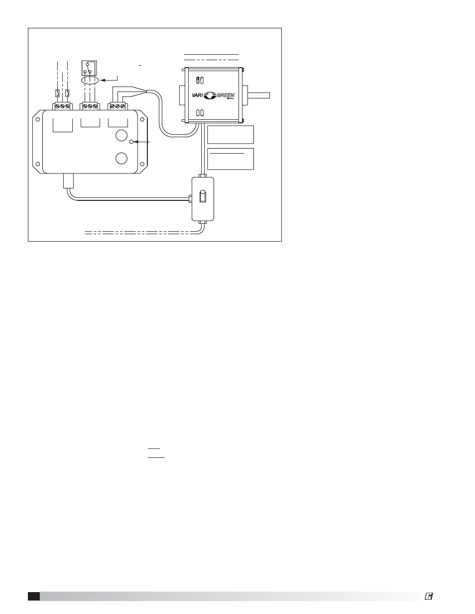
Installation Overview: The two speed control is factory
mounted to the fan and may be set to provide any two
speeds the application requires. It also includes a 24
VDC transformer. A green LED will be illuminated when
the 2-speed control is powered.
1. There are two methods of toggling between speed A
and speed B:
a. Dry contact input - this utilizes an external
switching device such as a relay or SPDT switch
to toggle between the two speeds.
• Connect terminal “A” to “COM” for speed A.
• Connect terminal “B” to “COM” for speed B.
If no contact is made between either terminal the
motor will be off.
b. AC Digital input - this input allows an AC voltage
signal to be fed directly into the 2-speed control
to change speeds.
• Send 115-230V AC to L1 OR L2 for speed B.
• Send 115-230V AC to L1 AND L2 for speed A.
If no voltage is applied to either terminal, the
motor will be off.
c. DO NOT CONNECT BOTH DRY CONTACT AND
DIGITAL INPUTS SIMULTANEOUSLY.
2. To test fan operation before the external control
devices are installed, a jumper wire can be
connected between the COM and A or B terminal on
the dry contact input for fan operation.
Troubleshooting - Two Speed
1. Check all wiring connections to ensure they are
correct and secure.
2. Verify AC line voltage is present at the motor and
2-speed control.
3. Verify 24V DC is present at the 24V and COM
terminals of the "Motor" terminal block.
4. Measure DC voltage between the 0-10V and COM
terminals of the "Motor" terminal block. This voltage
should match the dial position of the active dial.
a. If using dry contact input - ensure contact closure
is connecting the proper terminals.
b. If using AC digital input - disconnect connector
from 2-speed control and measure voltage
between L1 and Neutral or L2 and Neutral.
®
Factory Wiring
Field Wiring
*
NOTE:
Black wire not used
on some motors
Digital Input Logic
L1 or L2 = Speed B
L1 and L2 = Speed A
No input = Off
2 x 4
Junction
Box
115/230 VAC Input
to match motor name plate
Speed A
Adjustment
Speed B
Adjustment
Green indicator light
—Power present
FACTORY MOUNTED
2 SPEED CONTROL
Digital
Input
Dry
Contact
Input
L2
(115V
-230V)
NEUTRAL
L1(115V
-230V)
COM
A
B
COM
24V
0-10V
Motor
Out
Red
Black
*
White
Low voltage (<10V), route
away from high voltage lines
and/or use shielded cable
100' or less
SPDT
Switch/Relay
by others
115-230 VAC
NEUTRAL
115-230 VAC
2 Speed Assembly
Two Speed Assembly
®