Set point loop, Heat settings, Heat override – Greenheck Temperature Control Package v2.0 (461468) User Manual
Page 4: After-coil setting, Operating set points, Economizer (visible with internal economizer only), Mode, Ret to fact defaults
4
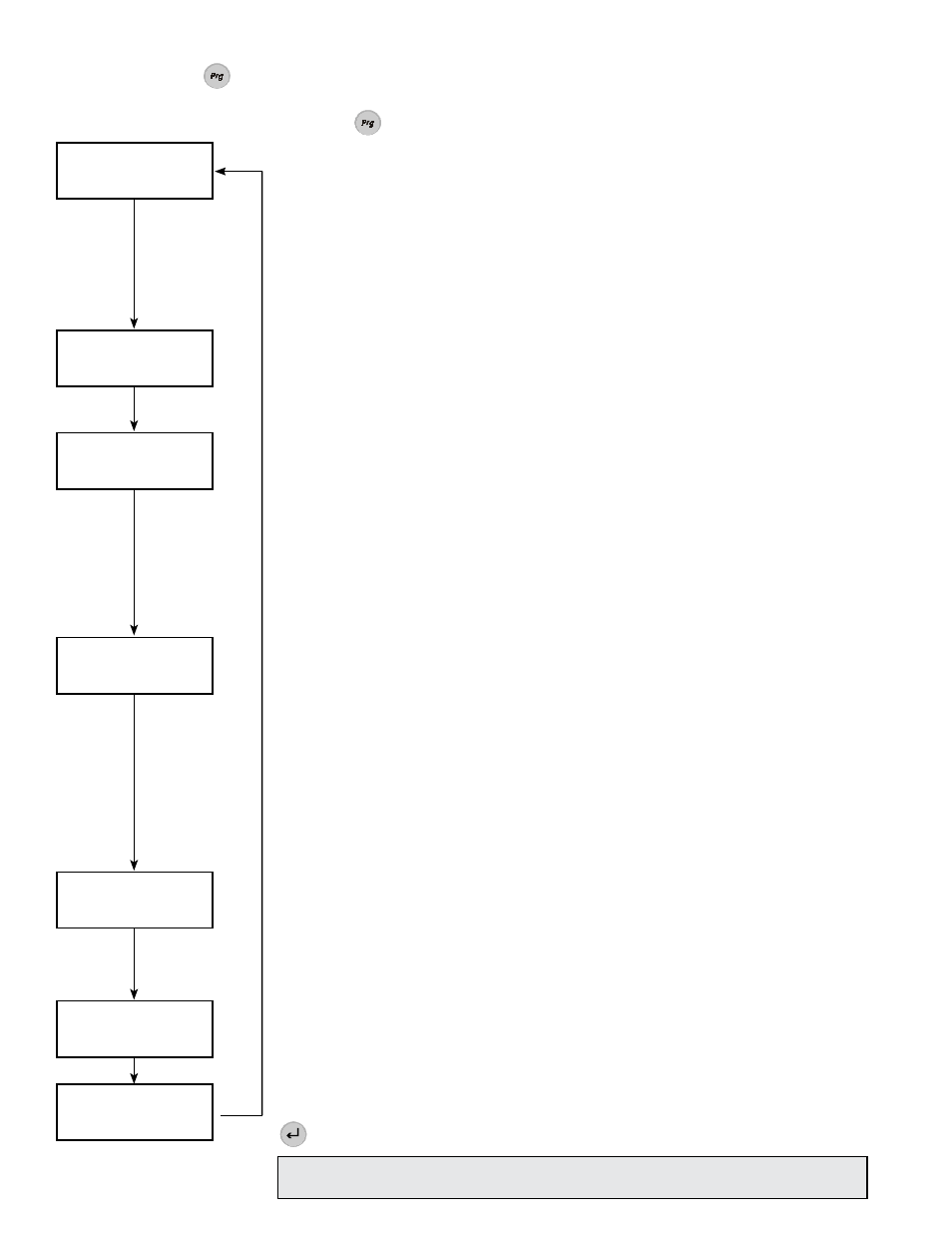
Set Point Loop
All temperature settings may be accessed in the set point loop; default temperature settings are shown on the
left. To access the Set Point Loop, press .
Operating Set Points
Change Enth 21.0B/lb
Freeze
35.0F
After Coil Setting
Typical
55.0F
Override
45.0F
Heat Settings
Summer
60.0F
Winter
70.0F
Heat Override
Summer
45.0F
Winter
95.0F
Heat Settings
No Room Thermostat
If reheat in the summer is required, adjust the summer heat setting to the desired
discharge temperature. If no reheat is required, set the summer temperature
below the after-coil setting. Adjust the winter set point to the desired discharge
temperature.
With Room Thermostat
The winter heat setting is the temperature the unit will discharge when the
thermostat is satisfied.
Heat Override
Only applicable on units with Room Thermostat
The summer set point is the temperature the unit will discharge when the
thermostat is calling for cooling in the summer. The winter set point is the
temperature the unit will discharge when the unit is calling for heat in the winter.
After-Coil Setting
No Room Thermostat or Humidistat
The typical setting is the desired temperature leaving the cooling coil. The
override setting is not applicable when no thermostat or humidistat is hooked to
the controller.
With Room Thermostat and/or Humidistat
The typical setting is the temperature after the cooling coil when the thermostat
is satisfied. The Override is the after-coil temperature when the room is above the
summer thermostat setting or when the room humidity is higher than the humidity
set point.
Operating Set Points
Change Enth
Change Enth is the enthalpy at which the controller will switch from summer to
winter operation. This set point has a factory programmed 0.5 btu/lbm dead-
band built-in to prevent the unit from rapidly switching from summer to winter
operation.
Freeze (Visible with Chilled Water Coil only)
The controller protects chilled water coils from freezing. When conditions before
the coil fall below the field-adjustable set point, the controller opens the water
valves completely, shuts down the supply fan and energy wheel, and sounds an
alarm on the controller in the unit. The controller also outputs a 10 VDC signal that
may be monitored remotely.
Economizer (Visible with Internal Economizer only)
“Set” is the enthalpy at which the energy wheel will be de-energized for “free
cooling” conditions.
“Band” is the range above and below the set point that the wheel will be de-
energized. (i.e. For the default setting, the wheel will be de-energized between 18
and 24 Btu/lb.)
Mode
“Auto” allows all features to operate as programmed on the controller.
“On” overrides the functionality of the controller (i.e. the supply blower, exhaust
blower and the energy wheel will always be energized).
Ret to Fact Defaults
“On” returns all settings to the original factory settings. Once “On” is selected and
is pressed, the display resets to the “Off” selection.
Economizer
Set
21.0 B/lb
Band
3.0 B/lb
Mode
Unit:
Auto
Ret to Fact Defaults
Off
CAREL
p
CO
2
built-in terminal
CAREL
p
CO
2
built-in terminal
CAREL
p
CO
2
built-in terminal
WARNING! When Return to Factory Defaults is turned to “On”, the blowers,
energy wheel and tempering options will be energized.