Wall mounting, Assemble weatherhood, Motor and pulley mounting – Greenheck SAF (468410) User Manual
Page 3
3
Centrifugal Roof Supply Air Fans
Wall Mounting
Only the 110 model is designed for wall mounting.
Do NOT attempt to wall mount the 112, 115, 118
or 120 models.
1. Refer to the instructions, warnings and notes found for
roof mounting.
2. Masonry Wall. Around the wall opening, install an angle
iron frame at least 2 x 2
x 1/4 inch to match the
inside base dimension of
the ventilator. Secure with
lead cinch type anchors
with non-ferrous bolts, not
supplied (3 per side). The
ventilator should then be
mounted (inlet assembly
down) to the mounting angle
with self-tapping sheet
metal screws (not supplied)
as shown in Figure 8.
Assemble Weatherhood
NOTE: Assembly requires a 3/8 inch nut runner.
1. Remove top cover.
2. Carefully remove weatherhood assembly and filters from
inside unit.
3. Slide weatherhood into place as shown in Figure 12.
Weatherhood flange should be on the inside of the unit.
4. Attach weatherhood by using 3/8 inch nut runner. Drive
the provided 1/4 inch thread rolling screws through the
side panel and into the weatherhood.
5. Loosen the thumb screws on the filter racks. Install filters.
Be sure the filters are properly oriented (airflow directions
are located on the side of the filter). Slide filter rack back
into place and tighten thumb screws.
6. Reinstall top cover.
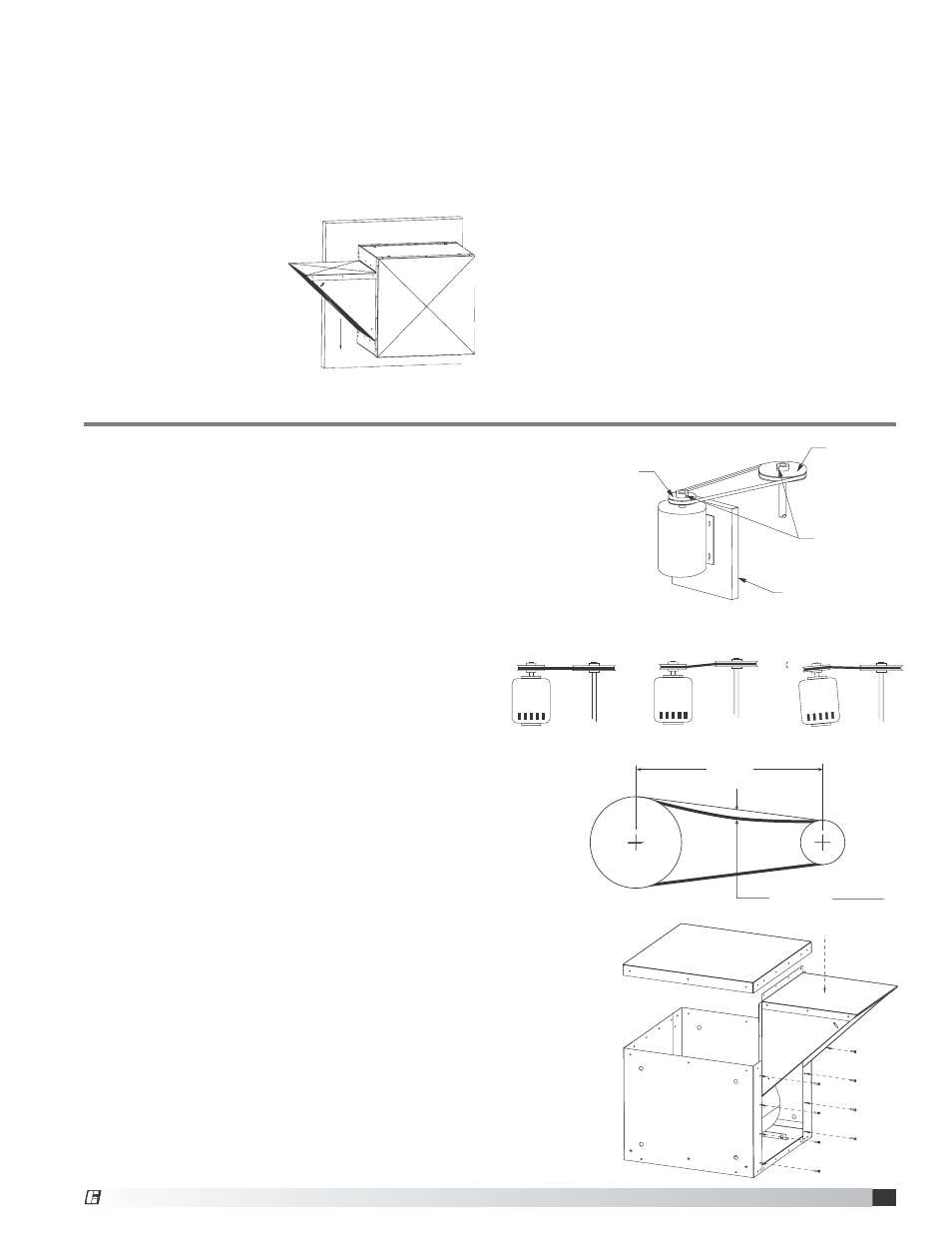
Motor and Pulley Mounting
NOTE: For Ul listed units, the motor used with this fan
must be designated as such by Greenheck Fan Corp.
1. Secure motor to plate using hardware provided. Holes
will align when the motor frame (shaft end) is flush with
the edge of the motor plate. See Figure 9.
2. Mount pulleys on shafts securing to shaft with set screw.
Check pulleys for proper alignment. Refer to Figure 10.
Misaligned pulleys lead to excessive belt wear, vibration,
noise and blower loss.
3. Install the belt and adjust the tension to allow for
1/64 inch of deflection per inch of span when moderate
thumb pressure is applied to the belt. Too much tension
will cause excess bearing wear and noise. Too little
tension will cause slippage at startup and uneven wear.
Refer to Figure 11.
4. Adjust RPM to desired level using a variable pitch pulley.
After adjustment, motor amperage should be checked to
avoid overloading of the motor.
3. Wood Siding. Around the wall opening install a wooden
frame at least 2 x 4 in. to match the inside base
dimension of the ventilator. Secure with counter-sunk
expansion type lag bolts (not supplied, 3 per side). The
ventilator should then be mounted (inlet assembly down)
to the mounting frame with square head wood screws
(not supplied) as shown in Figure 8.
NOTE: The actual size of the wall opening is determined
by the duct size.
4. Any mounting flange connection between the wall,
mounting flange and the ventilator, should be coated with
a suitable caulking compound or approved waterproof
mastic sealer to prevent water leakage into the ventilator.
5. It is recommended to install the unit with the inlet
assembly installed in a horizontal position (left or right
install configuration only). The inlet assembly must
be rotated so that the filters point in a downward
configuration, as shown in Figure 8.
Deflection (in.) =
Belt Span (in.)
62.5 (in.)
Belt Span
Figure 11 -
Belt Tension
MOTOR PLATE
SETSCREW
SHAFT PULLEY
FIXED PITCH
TYPE.
MOTOR PULLEY
VARIABLE PITCH
TYPE.
Figure 9 - Drive Package Diagram
Figure 12 -
Weatherhood Assembly
Belt Span
Deflection = Belt Span
64
Clockwise
CORRECT
WRONG
WRONG
WRONG
Belt Span
Deflection = Belt Span
64
Clockwise
CORRECT
WRONG
WRONG
WRONG
Belt Span
Deflection = Belt Span
64
Clockwise
CORRECT
WRONG
WRONG
WRONG
Figure 10 - Pulley Alignment
Figure 8 - Wall Installation
®
®