Installation, Roof mounting, Models 120 – Greenheck SAF (468410) User Manual
Page 2
2
Centrifugal Roof Supply Air Fans
Installation
Roof Mounting
Installation, troubleshooting and parts replacement is to
be performed only by a qualified personnel. Consult and
follow NFPA 96 recommendations. NFPA 96 instructions
supersede this document.
NOTE: Refer to motor nameplate for wiring procedures.
Refer to switch manufacturer for installation and
wiring procedures.
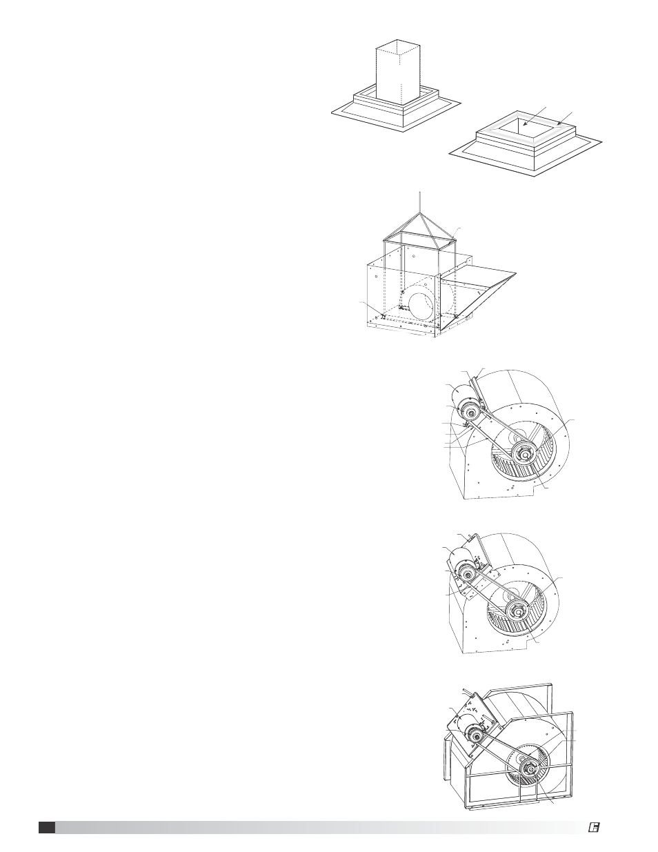
1. Cut an appropriate sized hole in the roof surface. Follow
curb manufacturer’s installation instructions. Caulk and
flash curb to ensure a water tight seal.
2. Position curb/equipment support(s) on the roof.
3. Good duct practices should be followed in accordance
with SMACNA and AMCA guidelines, NFPA 96 and any
local codes. The ductwork should extend far enough
above the roofline to meet the supply unit once it is
installed. See Figure 2.
4. Before installing supply unit, apply a sealant around
the perimeter of the supply duct to isolate the fan and
minimize vibration. See Figure 3.
5. Use a crane and set of spreader bars hooked to the
factory lifting holes (as shown in Figure 4) to lift and
center the unit on the curb. Use self-tapping sheet metal
screws to fasten unit to the curb.
NOTE: The use of all lifting holes and set of spreader
bars is mandatory when lifting unit.
6. For unassembled units, or when motor and drive is
shipped loose, install the motor and drive package as
shown in Figures 5, 6 and 7.
MODElS 110, 112, 115 and 118 -
Figure 5
(Motor Frame Sizes 56 and Smaller)
MODElS 110, 112, 115 and 118 -
Figure 6
(Motor Frame Sizes 143T and Larger)
a. Install blower sheave and motor sheave.
NOTE: On some units, a bushing may be required on
blower sheave.
b. Bolt the belt tensioning bracket to the motor using one
square head bolt and nut. Snap the rubber cap onto
the head of the tensioning screw. Thread the screw
through the tapped hole on the belt.
c. Slide the remaining two square head bolts down the
U-channel attached to the blower housing.
d. Align the slots/holes of the motor base plate with the
two square head bolts, attach the motor with remaining
two nuts.
e. Refer to page 3 for Motor and Pulley mounting
MODElS 120 -
Figure 7
a. Install blower sheave and motor sheave.
NOTE: On some units a bushing may be required on
blower sheave.
b. Align the motor with the appropriate holes in the motor
mounting plate. Bolt the motor to the motor mounting
plate using the four bolts and nuts provided. Make
certain to align the sheaves properly.
c. Refer to page 3 for Motor and Pulley mounting
instructions.
SPREADER BARS
LIFTING HOLE
Figure 4 -
lifting Unit
BELT
BUSHING
MOTOR
MOTOR SHEAVE
BLOWER SHEAVE
ADJUSTMENT
SLOTS
Figure 6 - Drive
Package Assembly
MOTOR SHEAVE
ADJUSTMENT
SLOTS
MOTOR
BELT
BLOWER
SHEAVE
BUSHING
Figure 7 - Drive
Package Assembly
Supply
Ductwork
by Others
Figure 2 -
Installing Ductwork
Sealant
Ductwork with duct
adapter installed
Figure 3 -
Applying Sealant
BLOWER SHEAVE
BELT
BUSHING
U-CHANNEL
MOTOR SHEAVE
SQUARE HEAD
BOLT/NUT (2)
MOTOR
TENSIONING
SCREW
RUBBER CAP
BELT
TENSIONING
BRACKET
Figure 5 - Drive
Package Assembly
®
®