Grease trap installation, Hinged base – Greenheck CUE/CUBE (471560) User Manual
Page 6
6
Upblast Centrifugal Roof Exhaust Fans
Grease Trap Installation
Polypropylene trap designed to collect grease residue to
avoid drainage onto roof surface. Follow all local codes,
as well as the National Fire Protection Agency (NFPA)
where applicable.
NFPA 96: Upblast fans shall have a drain directed to a
readily accessible and visible grease receptacle not to
exceed 1 gal. (3.8L)
Refer to Document 476370 - Grease Trap installation
Installation, Operation and Maintenance Manual for
parts listing and specific instructions.
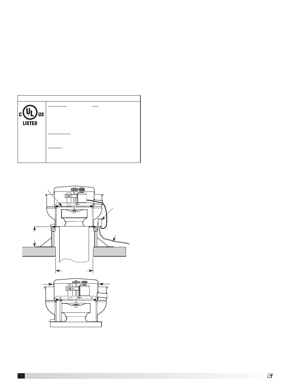
Factory
Installed
Heat Baffle
8 in. (203 mm)
minimum
Recommended
Roof Opening
NEMA-3R
Disconnect
factory wired
from motor to
disconnect
through the
breather tube
Liquid Tight
Flexible Conduit
by Others
Roof Deck
Recommended Emergency Smoke
Control Installation
Electric Connection
Emergency Smoke Control
The motor’s amperage and voltage rating must be
checked for compatibility to the supply voltage prior to
final electrical connection. Also, the motor itself cannot
have thermal overload.
For emergency smoke removal application, the electrical
supply must enter the motor compartment through the
breather tube. Disconnect must be mounted outside the
fans motor compartment. Consult local code authorities
for your specific requirements. Shown below is the UL
Listed label that the fan will bear.
For belt drive units in emergency smoke removal
installations, the electrical supply must be kept out of
the airstream. They may also require an isolated power
supply so that if power is cut to the building in the event
of a fire, the fan will continue to operate. Check the local
and national electrical codes for emergency
smoke removal fans.
Screw
Screw
IMPORTANT
Power
Ventilator
For Smoke
Control
Systems
76Y9
ELECTRICAL - If fan motor is NOT thermally protected,
remote overload protection must be installed having
adequate rating as to voltage, frequency, horsepower, and
full load current per phase. Where connected to a circuit
protected by fuses, use time delay fuses. For supply
connection use wires rated for at least 194˚F (90˚C).
INSTALLATION - When connecting electrical power to this
fan, do not restrict motor movement for possible future belt
or wheel adjustment.
CAUTION - Mount with the lowest moving part at least
8 ft (2.5m) above floor or grade level. Not required on roof
mounted ventilators or duct mounted ventilators provided
with belt guards.
Grease Trap Maintenance
Regular inspection of grease trap is recommended.
Depending on the amount of grease discharged through
the fan, the grease trap should be changed accordingly
to ensure proper operation.
• Check grease absorber (if included) every month.
Replace grease absorber after every cleaning and/
or as needed between cleanings.
• Replacement grease absorbers (P/N 476084) can
be ordered from your local Representative.
Hinged Base
NFPA 96: A hinged base is required on upblast fans and
in conjunction with grease trap accessory.
Refer to Document 462865 - Hinge Kit Installation,
Operation and Maintenance Manual for parts listing
and specific instructions.
®