Cue - direct drive, Cube - belt drive, Installation – Greenheck CUE/CUBE (471560) User Manual
Page 4: Typical wiring diagram, Caulk and rb to ater, Important
4
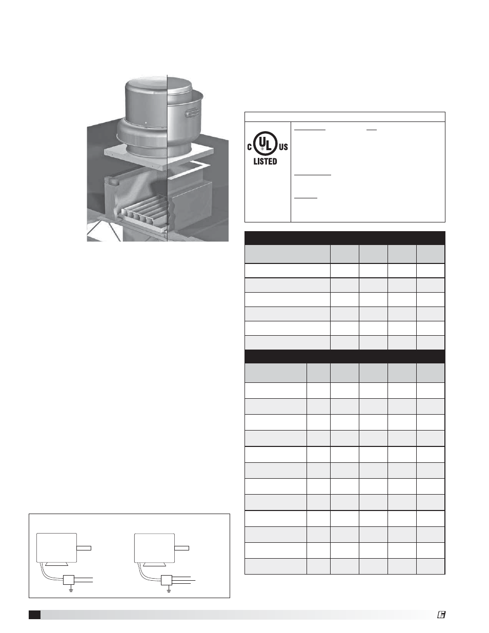
Upblast Centrifugal Roof Exhaust Fans
Installation
Typical Roof Mounting Installation
1. On the roof surface, cut an appropriate sized hole
and follow manufacturer’s instructions on curb
installation. Caulk and
flash the curb to
ensure a water
tight seal.
2. If unit is equipped with a backdraft damper, it
should be installed now.
3. Remove motor cover. Access to the motor
compartment is accomplished by removing the
screws as shown in figure 3.
4. For CUBE Belt Drive fans only. On the drive frame
use the lifting lugs to lift and place the unit on top of
roof curb. (Refer to figure 2 on page 2).
5. Secure fan to curb using a minimum of eight lag
screws, metal screws or other suitable fasteners.
Shims may be required depending upon curb
installation and roofing material.
6. Verify power line wiring is de-energized before
connecting fan motor to power source.
7. Connect power supply wiring to the motor as
indicated on the motor nameplate or terminal box
cover. Check the power source for compatibility
with the requirements of your equipment.
8. Check fan wheel for free rotation, re-center if
necessary.
9. Check all fasteners for tightness.
10. Mount and wire safety disconnect switch under
motor cover. Wire control switches at ground level,
refer to figure 4.
CUE - Direct Drive
Model
Curb
Cap
Damper
Roof
Opening
*Approx.
Weight
CUE 060, 065, 070, 075
17
(432)
8
(203)
10
1
⁄
2
(267)
26
(12)
CUE 080, 085, 090
19
(483) 10 (254)
12
1
⁄
2
(318)
33
(15)
CUE 095
19
(483) 10 (254)
12
1
⁄
2
(318)
36
(16)
CUE 098, 099, 101, 121, 131
19
(483) 12 (305)
14
1
⁄
2
(368)
67
(30)
CUE 141, 161
22
(559) 16 (406)
18
1
⁄
2
(470)
85
(39)
CUE 180-200
30
(762) 18 (457)
20
1
⁄
2
(521)
142
(64)
CUBE - Belt Drive
Model
Curb
Cap
Shaft
Bearings
Damper
Roof
Opening
*Approx.
Weight
CUBE 098, 099, 101,
101HP, 121, 131
19
(483)
1
⁄
2
(19)
12
(305)
14
1
⁄
2
(368)
66
(30)
CUBE 141, 141HP,
161, 161HP, 161XP
22
(559)
1
⁄
2
(19)
16
(406)
18
1
⁄
2
(470)
87
(39)
CUBE 180
30
(762)
3
⁄
4
(19)
18
(457)
20
1
⁄
2
(521)
126
(57)
CUBE 180HP
30
(762)
1
(25)
18
(457)
20
1
⁄
2
(521)
126
(57)
CUBE 200
30
(762)
3
⁄
4
(19)
18
(457)
20
1
⁄
2
(521)
142
(64)
CUBE 200HP
30
(762)
1
(25)
18
(457)
20
1
⁄
2
(521)
142
(64)
CUBE 220, 220HP
34
(864)
1
(25)
24
(610)
26
1
⁄
2
(673)
174
(79)
CUBE 240, 240HP,
240XP
34
(864)
1
(25)
24
(610)
26
1
⁄
2
(673)
175
(79)
CUBE 300, 300HP,
300XP
40
(1016)
1
(25)
30
(762)
32
1
⁄
2
(826)
313
(142)
CUBE 360, 360HP,
360XP
46
(1168) 1
1
⁄
4
(32) 36 (914)
38
1
⁄
2
(978)
440
(200)
CUBE 420
52
(1321) 1
1
⁄
4
(32)
42
(1067)
44
1
⁄
2
(1130)
578
(262)
CUBE 480
58
(1473) 1
1
⁄
2
(38)
48
(1219)
50
1
⁄
2
(1283)
675
(306)
• All dimensions are in inches (millimeters). *Approximate weight shown in lbs. (kg.) is the
largest cataloged Open Drip Proof motor.
• The roof curb should be 1½ in. (38 mm) less than the curb cap to allow for roofing and
flashing.
Caulk and
rb to
ater
Roof Curb
Installation
MOTOR
L1
115/208-230/60/1
208-230/460/60/3
MOTOR
J-BOX
J-BOX
SUPPLY VOLTAGE
SUPPLY VOLTAGE
L2
L1
L2
L3
Typical Wiring Diagram
Fig. 4
IMPORTANT
Power
Ventilator
565L
ELECTRICAL - If fan motor is NOT thermally protected,
remote overload protection must be installed having
adequate rating as to voltage, frequency, horsepower, and
full load current per phase. Where connected to a circuit
protected by fuses, use time delay fuses. For supply
connection use wires rated for at least 194˚F (90˚C).
INSTALLATION - When connecting electrical power to this
fan, do not restrict motor movement for possible future belt
or wheel adjustment.
CAUTION - Mount with the lowest moving part at least
8 ft (2.5m) above floor or grade level. Not required on roof
mounted ventilators or duct mounted ventilators provided
with belt guards.
11. Replace motor cover.
12. For restaurant and UL Listed for smoke evacuation
applications, the electrical supply must enter the
motor compartment through the breather tube.
For other non-flammable applications the electrical
supply can be routed through the conduit chase
between the curb cap and the bottom of the motor
compartment.
®