Pre-startup checks, Warning, Avertissement – Greenheck BDF (458341) User Manual
Page 4
Belt Drive Duct Fan
4
®
Pre-Startup Checks
1. Check all fasteners for tightness. The wheel should
rotate freely and not rub on the fan panel venturi.
Turn the fan on momentarily to check for unusual
vibration or noise. Do not run the fan more than
a few seconds without being connected to the
system for which it was designed. Motor overloading
and burnout may result from lack of system static
pressure.
2. Inlet and discharge collars are provided for duct
connection. The inlet panel is removable for
attaching optional filter box accessory.
3. Wheel Rotation: Direction of wheel rotation is
critical. Check wheel rotation by momentarily
energizing the unit. Improper rotation will result in
reduced airflow and pressure capabilities. Rotation is
always in the same direction as airflow at the outlet.
See housing and wheel examples in Figure 4.
WARNING
Correct direction of wheel rotation is critical. Reversed
rotation will result in poor air performance, motor
overloading and possible burnout.
AVERTISSEMENT
La turbine doit impérativement tourner dans le bon
sens. Une rotation en sens inverse entraînerait de
mauvaises performances de soufflage, une surcharge
du moteur voire un grillage du moteur.
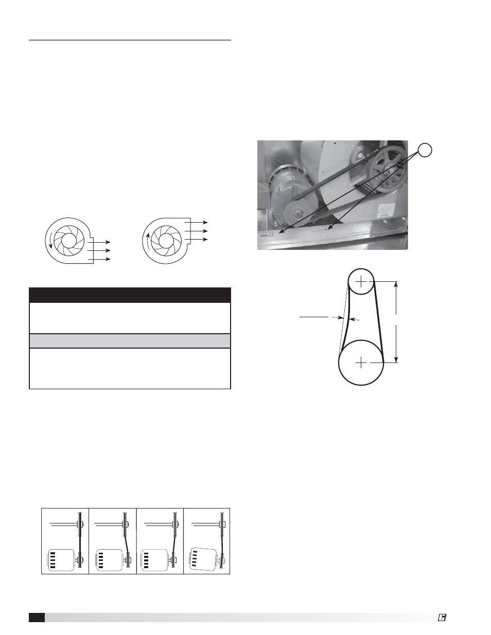
Belt Span
Deflection =
Belt Span
64
Figure 7
AIRFLOW
AIRFLOW
R
O
TA
T I O N
R
O
TA
T I O N
Figure 4:
Wheel Rotation Guide
Figure 5
Figure 6
R
4. Vibration Isolators: After fan is moved to desired
location, punch out the four knock-out holes which
are located on the unit top and bottom panels.
Assemble the brackets to the unit according to
the appropriate drawings on page 3 and refer to
respective parts list on page 7. Make certain all
connectors are tight and that all washers are in.
5 If adjustments are made, it is very important to check
the pulleys for proper alignment. Misaligned pulleys
lead to excessive belt wear, vibration, noise and
power loss. (See Figure 5).
6. Belt tension can be adjusted by loosening four
fasteners (marked “R”, Figure 6) on the drive frame.
The motor plate slides on the slotted adjusting arms.
Belt tension should be adjusted to allow 1/64 inch
of deflection per inch of belt span. For example, a
15 inch belt span should have 15/64 inch (or about
1/4 inch) of deflection with moderate thumb pressure
at mid-point between pulleys (See Figure 7).
Overtightening will cause excessive bearing wear
and noise. Too little tension will cause slippage at
startup and uneven wear.
WRONG
CORRECT
WRONG
WRONG
NOTE:
Identical
fasteners on
opposing
side must
also be
loosened.
7. The adjustable motor pulley is factory set for the
RPM specified. Speed can be increased by closing
or decreased by opening the adjustable motor
sheave. Two groove variable pitch pulleys must be
adjusted an equal number of turns open or closed.
Any increase in speed represents a substantial
increase in the horsepower required by a unit. Motor
amperage should always be checked to avoid
serious damage to the motor when speed is varied.