Greenheck MA6 Series (455410) User Manual
Page 4
9. Wire the actuator according to the appropriate wiring
illustration that identifies the actuator’s electrical
connections. Wiring should be per an approved
project or job wiring diagram and must comply with all
applicable electrical codes.
10. Apply power to the actuator.
The damper blades should fully open or close and
return to the fail position when power is disconnected.
If they do not, adjustments can be made by resetting
the crankarm position on the damper or actuator shaft,
or adjusting the 2 in. dimension discussed in Step #6d.
note: Motors in models MA6-318 and MA6-418 switch to
a hold winding at the end of their stroke. Motor may
overheat if stalled before cycling to the end of the
power stroke.
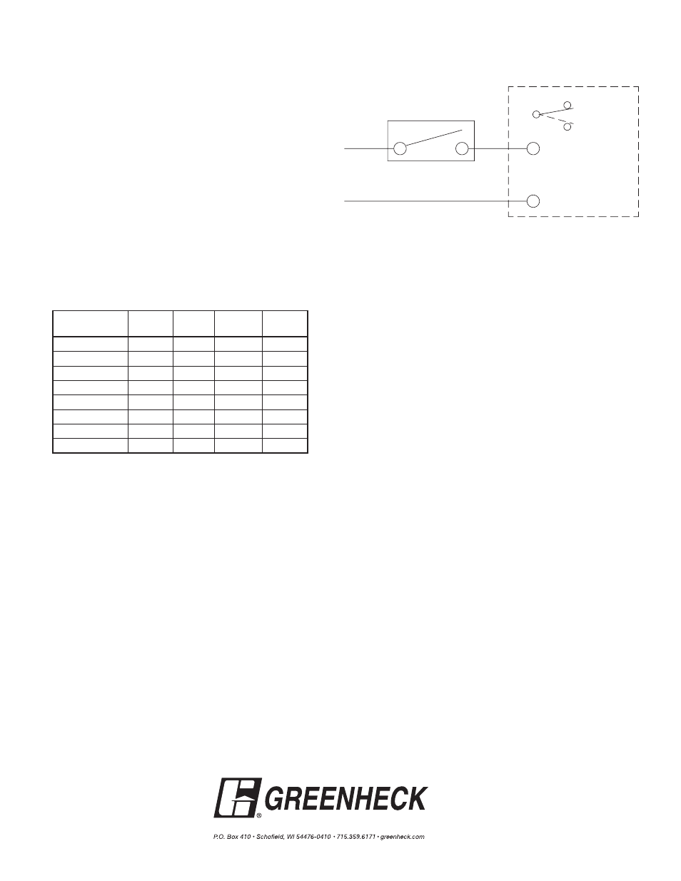
L1 or H
Aux. Switch (-500 Models)
L2 or G
Thermostat or Switch
Actuator
NC
NO
COM
Wiring Diagram for MA Series Actuators
H
G
Actuator Part Power
Aux.
VA*
VA*
Holding
number
supply switch running
MA6-305
24
No
56
56
MA6-305-500
24
Yes
56
56
MA6-405
120
No
48
48
MA6-405-500
120
Yes
48
48
MA6-318
24
No
92
32
MA6-318-500
24
Yes
92
32
MA6-418
120
No
108
42
MA6-418-500
120
Yes
108
42
Copyright © 2007 Greenheck Fan Corporation
455410 MA6 series Rev 4 September 2007
* Divide VA by the actuator voltage to get the amp draw.