Greenheck MA6 Series (455410) User Manual
Installation instructions, Invensys ma6 series
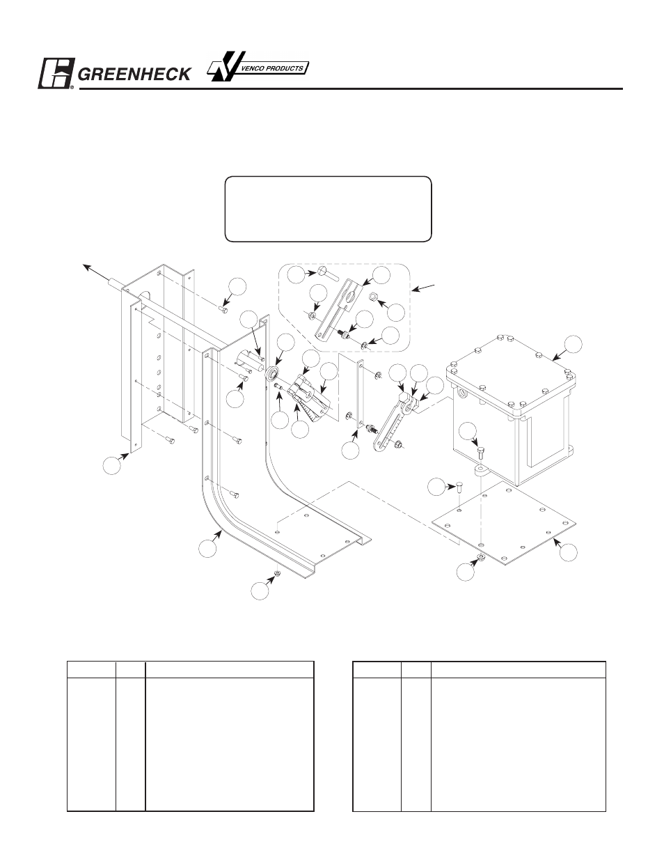
These instructions apply to the external field installation of Invensys actuators on Greenheck model VCD Control Dampers when
they are duct mounted or sleeved.
Invensys actuators rotate to their energized position when power is applied and spring return to their fail position when power is
interrupted.
20
19
18
17
15
16
13
14
11
12
10
1
2
3
4
5
6
7
8
9
6
7
8
9
6
1 in. Diameter Jackshaft Hardware
Replaces Items 7, 8, 9, & 19.
*Remove Bearing, Item 18,
If Using 1 in. Jackshaft
*
Co
ntrol Shaft
To Dampe
r
21
Part No. Qty. Description
1
1
Actuator
2
1
Mounting Bracket
3
1
Mounting Plate
4
4
1
/
4
-20 x
1
/
2
in. Thread stud
5
3
1
/
4
-20 x 1
1
/
4
in. HH Bolt
6
8
1
/
4
-20 Spinlock Nut
7
3
1
/
2
in. Crankarm
8
3
5
/
16
-18 x 1
1
Ú
2
in. Bolt
9
3
5
/
16
-18 Spinlock Nut
10
1
1 in. Crankarm
11
1
3
/
8
-16 x 2
1
/
2
in. Carriage Bolt
Part No. Qty. Description
12
1
3
/
8
-16 Spinlock Nut
13
1
Linkage Adjustment Pin
14
2
1
/
4
in. E-ring
15
1
Drive Link
16
1
Anchor Bracket
17
4
1
/
4
-20 x
1
/
4
in. Thread Cutting Screw
18
1
Press Fit Ball Bearing
19
1
1
/
4
x
1
/
2
in. Knurl Pin
20
8
#14 x
3
/
4
in. HWH Tek
21
2
#10 Tek Screw
Part #455410
Invensys MA6 series
UL Listed Electric Actuators with Two Position Control
InsTALLATIon InsTrUCTIons
Tools required:
Wrenches:
(1)
3
/
8
in., (2)
1
/
2
in., (1)
7
/
16
in., and (1)
9
/
16
in.
(1) Hammer