Electrical wiring, Start-up — blower – Greenheck KSFB / KSFD (463556) User Manual
Page 5
5
KSFB and KSFD Make-Up Air
®
Electrical Wiring
1. Determine the Size of the Main Power Lines:
The unit nameplate states the unit’s voltage and
total amps. The main power lines to the unit should
be sized accordingly.
2. Connect the Main Power: Connect the power
line to the disconnect switch. The electrical supply
must be compatible with the fan motor with
regards to voltage, phase, and amperage capacity.
Moreover, the electrical supply line must be
properly fused and conform to local and national
electrical codes. Electrical wires must be located
so as not to rub on moving components.
Start-Up — Blower
Pre-Start-Up Check: Rotate the fan wheel by
hand and make sure no parts are rubbing. Check
the V-belt drive (KSFB only) for proper alignment
and tension (a guide for proper belt tension and
IMPORTANT
Before connecting power to the unit, understand the
following instructions.
All wiring should be done in accordance with the
latest edition of the National Electrical Code ANSI/
NFPA 70 and any local codes that may apply. In
Canada, wiring should be done in accordance with
the Canadian Electrical Code.
CAUTION
If any of the original wire must be replaced, the
replacement wire must have a temperature rating
of at least 105°C. Any wiring deviations may result
in personal injury or property damage. Greenheck is
not responsible for any damage to or failure of the
unit caused by incorrect final wiring.
DANGER
High voltage electrical input is needed for this
equipment. This work should be performed by a
qualified electrician.
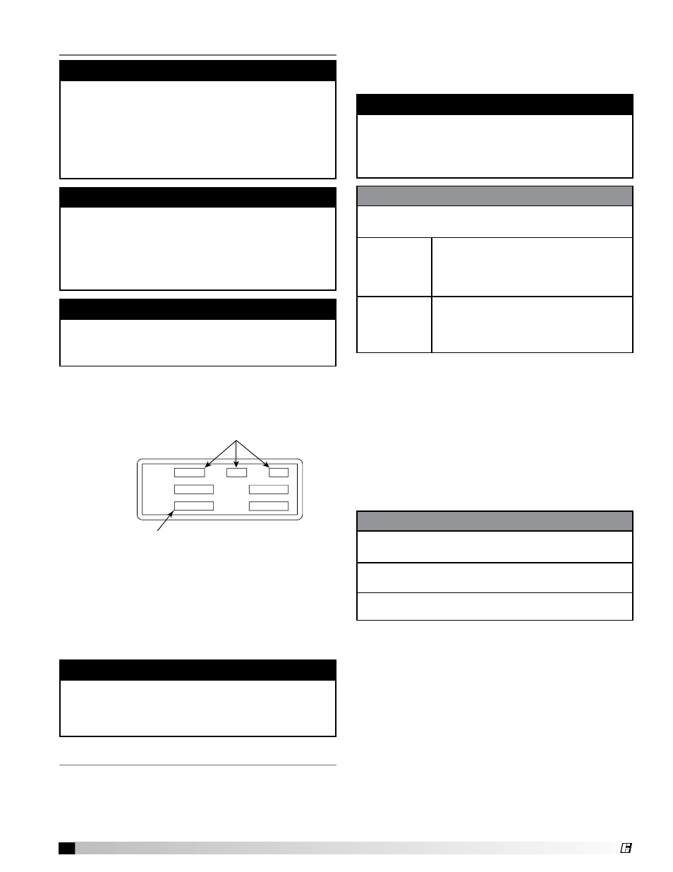
SUP HP
MCA
EXH HP
MOP
VOLTS
HZ
PH
Unit’s Total MCA
Voltage, Hertz, Phase
SUP HP
MCA
EXH HP
MOP
VOLTS
HZ
PH
Voltage, Hertz, Phase
alignment is provided in the belt maintenance section).
Check fasteners, set screws and locking collars on
the fan, bearings, drive (KSFB only), motor base and
accessories for tightness.
1. Check the Voltage: Before starting the unit,
compare the supplied voltage, hertz, and phase
with the unit and motor nameplate information.
2. Check the Blower Rotation: Remove the housing
cover and run the blower momentarily to determine
the rotation. Arrows are placed on the blower scroll
to indicate the proper direction. If the blower is
rotating in the wrong direction, the unit will move
some air, but will not perform as designed. Be sure
to perform a visual inspection to guarantee the
correct blower rotation.
3. Check for Vibration: Check for unusual noise,
vibration or overheating of the bearings and take
corrective action.
Excessive vibration may be experienced during
the initial start-up. Left unchecked, it can cause a
multitude of problems, including structural and/or
component failure.
Generally, fan vibration and noise is transmitted
to other parts of the building by the ductwork. To
minimize this undesirable effect, the use of heavy
canvas connectors is recommended.
4. Motor Check: Measure the motor’s voltage, amps
and RPM. Compare to the specifications. Motor
amps can be reduced by lowering the motor RPM
or increasing system static pressure.
IMPORTANT
If fan motor is not thermally protected, remote
overload protection must be installed having
the adequate rating as to voltage, frequency
horsepower, and full load current per phase.
WARNING
Disconnect and lock-out all power before performing
any maintenance or service to the unit. Failure to do
so could result in property damage and serious
injury or death.
TO REVERSE ROTATION
To reverse the rotation, disconnect and lock-out the
power.
Single Phase:
Rewire the motor per the
manufacturer’s instructions.
Three Phase:
Interchange any two power leads.
SPECIAL EQUIPMENT REQUIRED
Required and recommended tools. Equivalent
products may be used.
Voltage &
Amperage
Meter
Manufacturer: Fluke
Model:
177
Phone:
1-800-44-FLUKE
www.fluke.com
Tachometer
Manufacturer: Monarch
Model:
Pocket Tach 100
Phone:
1-800-999-3390
www.monarchinstrument.com