Electrical guidelines, Installation, Safety danger – Greenheck ICD Dampers (468333) User Manual
Page 2
2
safety DaNGeR !
electrical input may be needed for
this equipment. this work should be
performed by a qualified electrician.
electrical Guidelines
safety CaUtIoN !
Verify power requirements before wiring
actuator. Greenheck is not responsible for
any damage to, or failure of the unit caused
by incorrect field wiring.
Electrical and/or pneumatic connections to damper actuators should be made in accordance with wiring and piping
diagrams developed in compliance with applicable codes, ordinances and regulations.
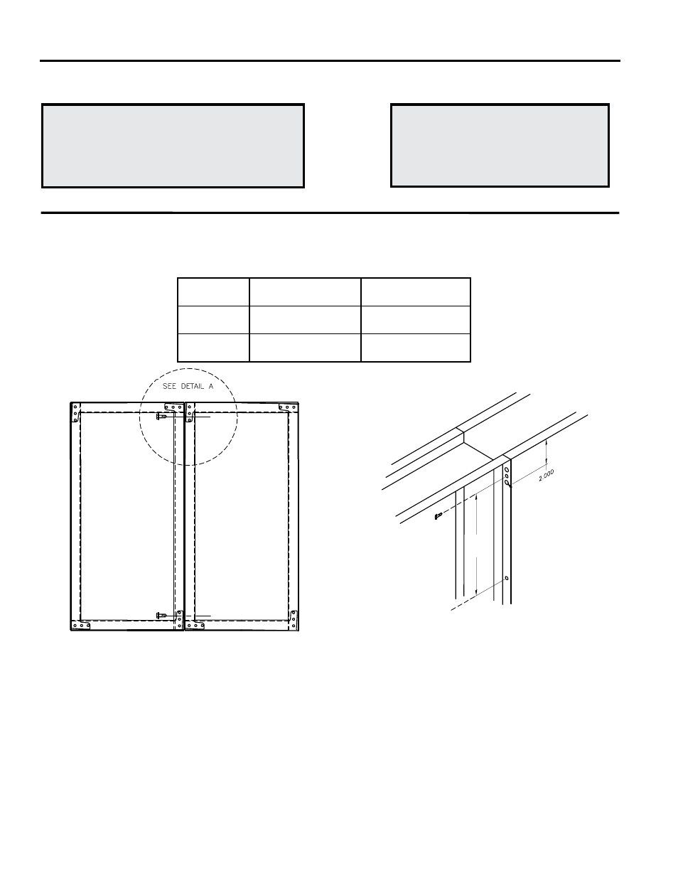
3. The damper sections must be attached together with #10 x 3/4 inch (19mm) max. sheet metal screws,
1/4 inch (6mm) diameter nuts and bolts, tack or spot welds or 3/16 inch (4mm) diameter steel pop rivets.
Attachments must be spaced a maximum of 6 inch (152mm) on centers and a maximum of 2 inch (51mm)
from corners. Attachments must be made on front face and back face ( air entering and air exiting side) of
damper sections (see Figure 1 & 2).
4. If no holes are present in frame, drill 1/4 inch (6mm) diameter holes at 6 inch (152mm) centers and fasten
frames together with 1/4 inch (6mm) #20 (.03mm) bolts and nuts.
5. Brace at every horizontal mullion and vertically brace at every 8 feet (2.4m) of damper width for strength.
Dampers in high velocity (2000 fpm [610m per second]) may require more bracing. Note: Greenheck
dampers are specifically designed and engineered for structural integrity based on model and conditions.
Attachment, framing, mating flanges, and anchoring of damper assemblies into openings, ductwork, or walls
is the responsibility of the installer. Design calculations for these retaining and supporting members should
be determined by field engineers for that particular installation.
Installation -
failure to follow instructions will void all warranties
1,
Duct opening or opening square should measure to the inside damper dimension and should be straight and
level.
2. A
damper assembly is not restricted to a maximum number of sections, but must not exceed the section
sizes and overall sizes shown below.
Damper Model
Maximum
Single Section Size
Maximum
Multi-Section Size
ICD-44
48 in. W x 74 in. H
(1219mm W x 1880mm H)
144 in. W x 148 in. H
(3658mm W x 3759mm H)
ICD-45
48 in. W x 74 in. H
(1219mm W x 1880mm H)
144 in. W x 120 in. H
(3658mm W x 3048mm H)
6.000
O.C.
MAX.
6.000
O.C.
MAX.
Figure 1
figure 2