Greenheck Hinge Kit Sizes 220-540 (462865) User Manual
Page 3
3
Hinge Kit
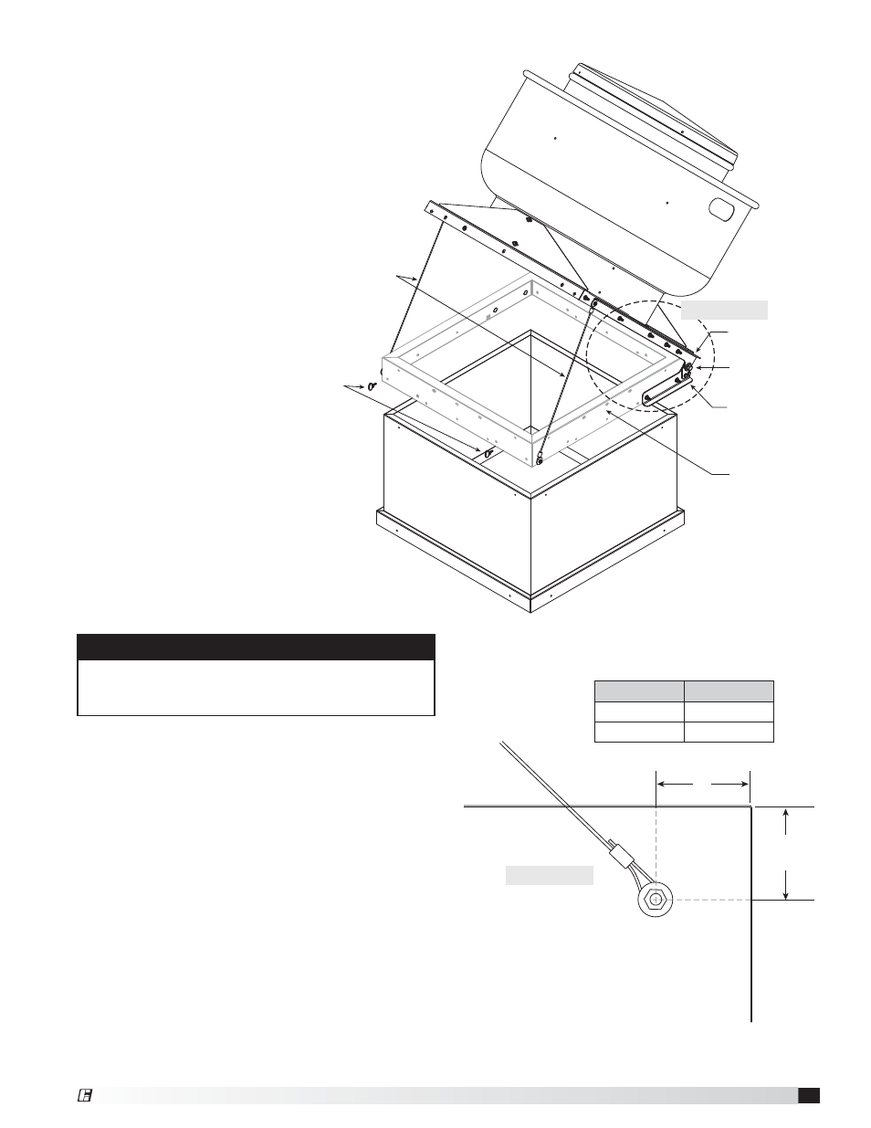
FIGURE 4
7. Install 5/16 inch weld bolts through lower hinge
into curb and install nuts. If necessary, disconnect
hinge bolt and remove unit from curb to install lower
hinge.
NOTE: If curb is of construction other than sheet
metal, use appropriate connector. For example,
if the curb is made of wood, use a lag bolt.
8. Attach the loose end of the stop cable to the curb
with appropriate fastener and fender washer.
See FIGURE 5 for hole location.
9. Wind gusts are capable of lifting the curb cap off
from the curb. Secure the curb cap to the curb
with the thumb screws provided with a hinge base
or other appropriate method.
CAUTION
Roof curb or extended base should be properly
attached to the roof to support the fan and curb when
moved to the open position.
6. Rotate the lower hinge
until parallel with the upper
hinge. If cap has factory
holes that line up with hinge
holes, go to Step 7. If cap
does not have matching
holes from the factory,
mark the hole locations in
the curb and drill a 5/16
inch hole at each location.
Reference FIGURE 4.
Dimension A
Model
8 inches
200 - 480
16 inches
500 - 540
Fan
Roof Curb
Stop Cables
Upper Hinge
Pivot Bolt
Lower Hinge
Thumb
Screws
Optional
Hinge Base
Steps 6 and 7
A
4 inches
(101.6 mm)
Step 8
FIGURE 5
®