Greenheck Hinge Kit Sizes 220-540 (462865) User Manual
Page 2
2
Hinge Kit
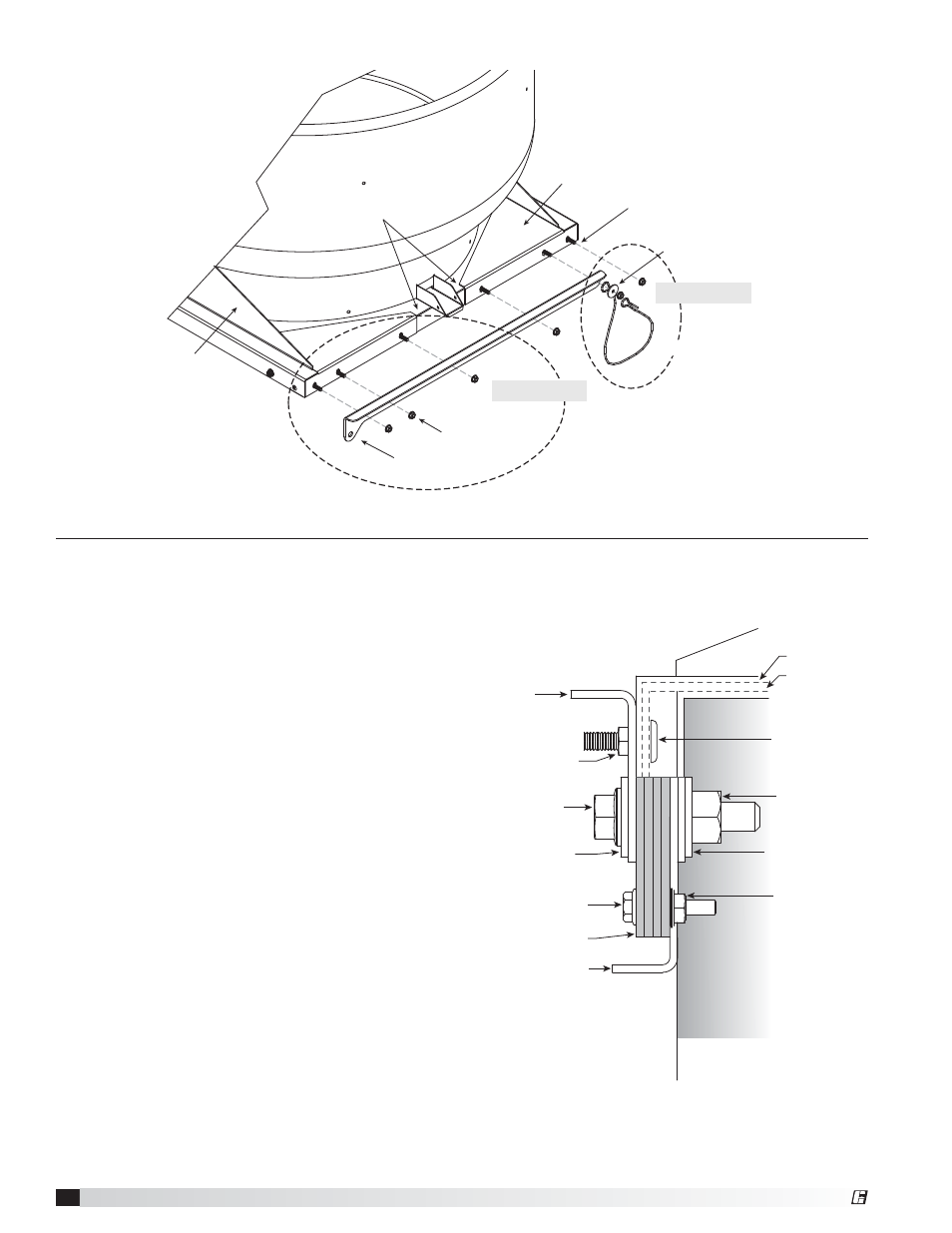
2. Place reinforcing assembly on the curb cap; loosely
install the four screws removed in Step 1.
If cap has factory holes that line up with hinge
holes, go to Step 3. If cap does not have matching
holes from the factory, mark the remaining hole
locations for drilling. Drill a 5/16 inch hole in the
curb cap at these locations.
3. Attach each top hinge and reinforcing assembly to
the curb cap with 5/16 inch - 18 x 1 inch long weld-
bolt screws and 5/16 inch spinlock nuts. Refer to
FIGURE 2.
NOTE: The stop cable is installed to the top hinge
under the nut furthest from the pivot point. Secure
the cable with the 5/16 inch x 1-1/4 inch fender
washer. Allow the opposite end to hang loose until
Step 8. FIGURE 2
4. Set unit on roof curb or hinge base. Center curb cap
on the curb or hinge base so there is equal space
around the perimeter. If curb cap has a hinge base,
align hold down screws with threaded holes and
loosely install thumb screws.
Refer to FIGURE 4.
5. Attach each lower hinge to the upper hinge with
the 1/2 inch - 13 x 2 inch bolt, 1/2 inch washers
and 1/2 inch nylock nut. Attach equal number of
hinge spacers to bottom hinge with 1/4 inch - 20 x
1-1/4 inch bolts and 1/4 inch nut to take up the gap
between the top and bottom hinges. THE NUMBER
OF SPACERS WILL VARY FROM UNIT TO UNIT.
Refer to FIGURE 3.
FIGURE 2
FIGURE 3 - Reinforcing Assembly
Weld Bolt
5/16-18 x 1
Fender Washer
5/16-18 x 1
Curb Cap
Nut 5/16-18
Top Hinge
Reinforcing
Assembly
Plate
Reinforcing
Assembly
Plate
Steps 2 and 3
Step 4
Restaining Cable
Restaining Cable
Bolt
1/2-13 x 2
Weld Bolt
5/16-18 x 1
Flat Washer
1/2 x 1-1/16
Flat Washer
1/2 x 1-1/16
Bolt
1/4 x 20 x 1¼
Nut 5/16-18
Nut 1/2-13
Nut 1/4-20
Inside of curb
Top
Hinge
Hinge
Frame
Fan Curb
Cap
Bottom Hinge
Hinge Spacer
®