System installation – Greenheck Energy Recovery Filter Hood System User Manual
Page 3
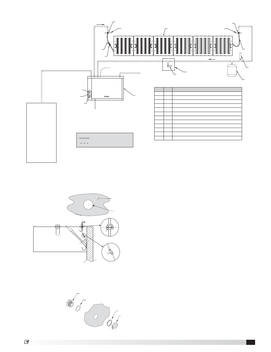
System Installation
FROM WATER
SUPPLY LINE
1 INCH FNPT CONNECTION
TO WATER HEATER
WATER
HEATER
TO FIL
TERS
FROM FILTERS
FLOW
FLOW
*HOOD PENETRATION
*HOOD PENETRATION
1 INCH FNPT CONNECTION
3/4 INCH FNPT CONNECTION
3/4 INCH FNPT CONNECTION
1
2
4
3
5
*6
7
8
9
*6
10
11
TO DRAIN
3/4 INCH FNPT CONNECTION
12
PIPING PROVIDED BY OTHERS
MUST BE IN ACCESSIBLE
LOCATION FOR TESTING
Quantity of filters varies based on hood size
*TOP, SIDE, OR BACK OF HOOD. TO BE COMPLETED IN FIELD BY OTHERS.
DO NOT OBSTRUCT FIRE SYSTEM PIPING.
ELECT.
120 VAC 15 AMP
FROM BREAKER
ITEM QTY DESCRIPTION
1
1
Control
Cabinet
2
1
No Flow Status Light
3
1
Pushbutton Switch, System ON/OFF
4
1
Pushbutton Switch, Pressure Release
5
Varies
Filter Assembly (quantity varies based on hood size)
*6
2
3/8-inch FNPT Hood Penetration Seal, (1
1
/
8
inch hole)
7
1
18 inch Stainless Steel Hose
8
1
3/8-inch Quick Disconnect
9
1
24-inch Stainless Steel Hose
10
1
Thermal Expansion Tank (provided by others)
11
1
Water Hammer Arrestor (provided by others)
12
1
1/4 Turn Ball Valve to Test Flow Rate (provided by others)
ELECTRICAL PROVIDED BY OTHERS
1. Remove the existing filter(s) from commercial kitchen
hood for retrofit or from the shipping container for a
new installation.
2. Drill two 1
1
⁄
8
-inch holes in the hood top, side or back
above the filter
rack, one close
to the left and
one close to the
right side of the
hood.
3. Install a hood penetration seal (item 6) in the hood
top above the filter rack. To do this, disassemble the
compression seal and insert the seal into the hole
from the inside of the hood making sure the gasket is
placed on the
fitting before
inserting it
into the hole.
Install the lock
washer and
nut and tighten
securely as
shown.
4. Attach the 18 inch stainless steel hose (item 7) to
the left-most hood penetration seal, and the 24 inch
stainless steel hose (item 9) to the right-most hood
penetration seal.
5. Attach the extra female coupler to the 18 inch hose
(item 7) on left end of the hood, and the male coupler
to the 24 inch hose (item 9) on the right end of the
hood.
6. Install new filters in hood from left to right. Hook
up the quick-connect couplers between the filter
assemblies.
7. If applicable, install adjustable filter spacers to fill in
the gap(s) on the hood ends.
8. Install all other plumbing, as shown on this drawing.
Please refer to plumbing requirements section on
page 4 for more information.
9. Make all of the electrical connections. Please refer to
electrical requirements section on page 4 for more
information.
1-1/8 inch
(2.86 cm)
diameter hole
Hood Surface
Nut
Lock Washer
EXTERIOR OF HOOD
INTERIOR
OF HOOD
Hood
3/8 inch UL Listed Hood Penetration Seal
PN 451167
Gasket
7
8
6
9
Energy Recovery Filter System
3