Table of contents installation, Category pages – Greenheck Duct Heaters Series IDHB and IDHC (478052) User Manual
Page 2
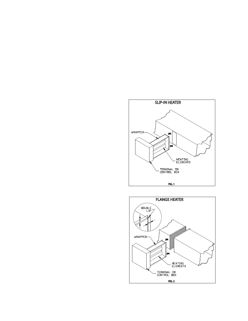
Table of Contents
Installation -
Failure to follow instructions will void all warranties.
For safe operation and best performance, the following installation procedures must be adhered to.
Heaters may be installed in the sides of either horizontal or vertical ducts but never in the top or bottom of a
horizontal duct. Heaters installed in vertical ducts are tested and approved for up airflow only!
1. Install heater a minimum of (4) feet from heat
pumps or central air conditioners.
2. At least 4 feet downstream from an air
handler.
3. At least 2 feet either side of an elbow or
turn.
4. At least 4 feet from any canvas duct
connector or transition section for change in
duct size.
5. At least 4 feet downstream from an air filter.
6. At least 4 feet upstream from a humidifier.
Refer to the back of this sheet for duct, electrical and
air velocity requirements.
To install a slip-in heater (FIG.1), cut an opening as
required in the side of the duct. Slide heater in the
duct using the control box as template to mark the
mounting screw holes. Remove unit and drill mounting
holes. Mount unit to duct with sheet metal screws.
Connect high and low voltage supplies along with
fan interlock circuit (if no airflow switch is furnished).
Larger heaters may require hangers.
To install a flange type heater (FIG.2), insert heater
between two sections of flanged duct, and bolt in
place. For additional strength, the duct flange should
be doubled as shown in the figure. Large heaters may
require hanger straps. Connect high and low voltage
supplies along with fan interlock circuit (if no airflow
switch is furnished).
The air duct should be installed in accordance with
the Standards of the National Fire Protection Agency
for the Installation of Air-Conditioning and Ventilating
Systems (Pamphlet No. 90A) and Warm-Air Heating
and Air-Conditioning Systems (Pamphlet No. 90B).
Do not “bank” heaters (side by side). If greater
capacity is required, proportion smaller heaters in
separate runouts.
Heater control boxes must be completely accessible
and located to provide ventilation at all times.
SLIP-IN HEATER
FIG. 1
FIG. 2
FLANGE HEATER
HEATING
ELEMENTS
TERMINAL OR
CONTROL BOX
WRAPPER
WRAPPER
TERMINAL OR
CONTROL BOX
HEATING
ELEMENTS
1"
1"
DOUBLE
LIP
SLIP-IN HEATER
FIG. 1
FIG. 2
FLANGE HEATER
HEATING
ELEMENTS
TERMINAL OR
CONTROL BOX
WRAPPER
WRAPPER
TERMINAL OR
CONTROL BOX
HEATING
ELEMENTS
1"
1"
DOUBLE
LIP
Category Pages
Installation ....................................................................................................................................................................2
Electrical Requirements ...............................................................................................................................................3
Minimum Air Velocities .................................................................................................................................................4
Insulated Duct Installation ...........................................................................................................................................5
Heaters with SSR or Electronic Step Controllers ........................................................................................................6
Troubleshooting Guide ............................................................................................................................................. 6-8
2