Delta Electronics SMT Power Inductor SIR85 User Manual
Smt power inductor, Sir85 type, Electrical characteristics: features
16
SMT Power Inductor
SIR85 Type
DELTA ELECTRONICS, INC.
(TAOYUAN PLANT CPBG)
252, SAN YING ROAD, KUEISAN INDUSTRIAL ZONE, TAOYUAN SHIEN, 333, TAIWAN, R.O.C.
TEL: 886-3-3591968; FAX: 886-3-3591991
http://www.deltaww.com
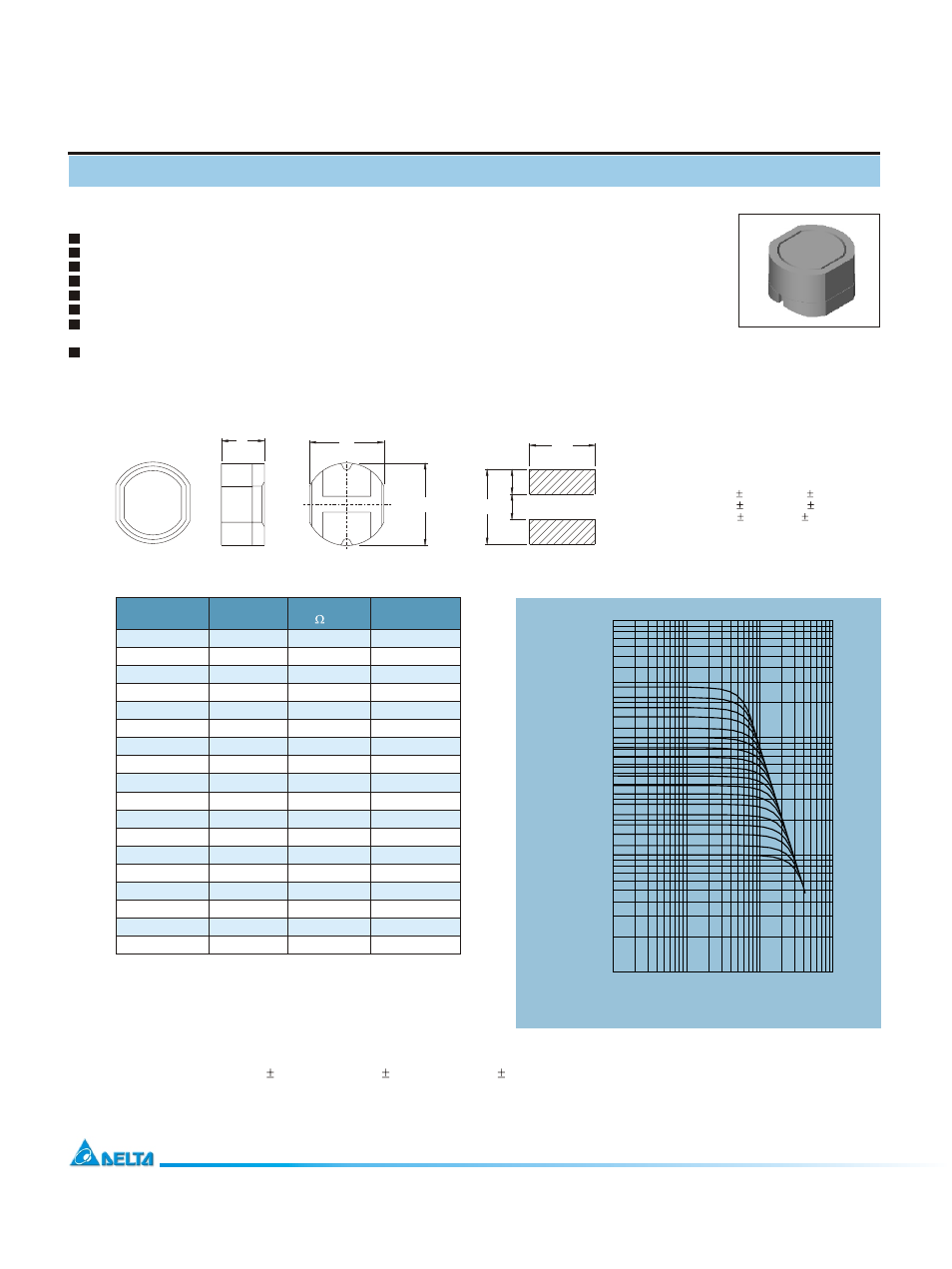
Electrical Characteristics:
Features
RoHS compliant.
Low profile (4.9mm max. Height) SMD type.
Magnetically shielded, suitable for high density mounting.
Self-leads, suitable for high density mounting.
High energy storage and low DCR.
Provided with embossed carrier tape packing.
Idel for power source circuits, DC-DC converter, DC-AC inverters
inductor applications.
In addition to the standard versions shown here, customized inductors
are available to meet your exact requirements.
0.01
0.10
1.00
10.00
CURRENT (A)
1.00
10.00
100.00
1000.00
IN
D
U
C
T
A
N
C
E
(u
H
)
100
120
150.
180
220
270
330
470
560
680
820
101
390
121
151
181
221
271
25
100KHz, 0.1V
o
C,
SIR85 - 100
10
0.070
1.65
SIR85 - 120
12
0.070
1.57
SIR85 - 150
15
0.080
1.39
SIR85 - 180
18
0.100
1.29
SIR85 - 220
22
0.130
1.12
SIR85 - 270
27
0.160
1.06
SIR85 - 330
33
0.180
0.97
SIR85 - 390
39
0.180
0.91
SIR85 - 470
47
0.270
0.80
SIR85 - 560
56
0.290
0.76
SIR85 - 680
68
0.330
0.68
SIR85 - 820
82
0.430
0.62
SIR85 - 101
100
0.490
0.55
SIR85 - 121
120
0.680
0.49
SIR85 - 151
150
0.940
0.44
SIR85 - 181
180
1.000
0.40
SIR85 - 221
220
1.180
0.36
SIR85 - 271
270
1.300
0.33
1. Tolerance of inductance: 20% for 10~27uH, 15% for 33~82uH, 10% for 100~270.
2. Irated is the DC current which cause the inductance drop 10% typical of its nominal inductance without current
and the surface temperature of the part increase less than 45
3. Operating temperature : -20
to 105
(including self-temperature rise).
o
C.
o
o
C
C
PART NO.
DCR
( ) MAX
2
Irated
(Adc)
1
1
L
(uH)
2.0
10
C
B
A
7.5
4.0
Mechanical Dimension:
UNIT:mm/inch
A = 7.8 0.35 / 0.307 0.014
B = 7.0 0.35 / 0.276 0.014
C = 4.5 0.4 / 0.177 0.016
¡У
¡У
¡У
¡У
¡У
¡У
RECOMMENDED PAD PATTERNS