Fronius Power Control Card User Manual
Page 46
44
Using the Fronius
Power Control
Card without a
ripple control sig-
nal receiver
Select either 2-relay mode or 3-relay mode on the "operating mode adjusting dial"
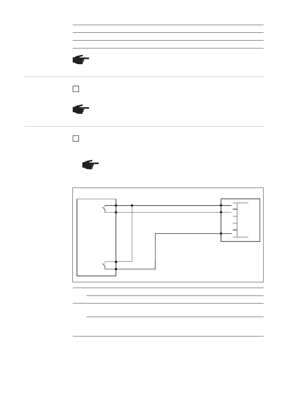
Connecting the
Fronius Power
Control Card to a
control unit in line
with Italian stand-
ard CEI 0-21
Connect the CEI 0-21-compliant control unit and Fronius Power Control Card plug us-
ing a 3-pin cable, as shown in the connection diagram below
Tightening torque for the terminals: 0.25 Nm
30%
open
closed
open
0%
open
open
closed
NOTE! Cables are not monitored in 3-relay operation. Cable breaks are not de-
tected and displayed as faults.
Power
Relay 1
Relay 2
Relay 3
NOTE! There is no reduction in power.
1
NOTE! The terminals on the plug for the CEI 0-21-compliant control unit are
designed to accommodate a maximum cable cross-section of 1.5 mm².
A screened cable is recommended if the distance between the Fronius Pow-
er Control Card and the CEI 0-21-compliant control unit is greater than 10 m.
CEI 0-21-compliant control unit
Fronius Power Control Card
(1)
closed
Enforced inverter standby mode (no energy fed into the grid)
open
Normal inverter operating mode
(2)
closed
Activation of the inner S1 frequency thresholds and the outer
S2 frequency thresholds as per CEI 0-21
open
Deactivation of the inner S1 frequency thresholds
Activation of the outer S2 frequency thresholds
as per CEI 0-21
1
(1)
1
2
34
5
GND
D1
D2
D3
D4
(2)