Fronius Power Control Card User Manual
Page 44
42
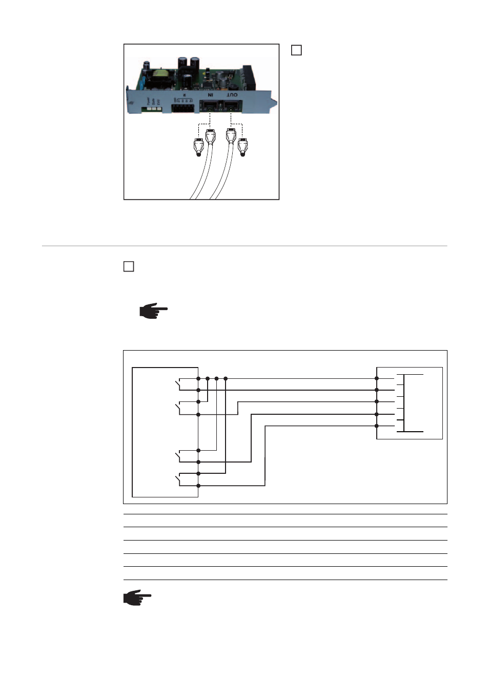
Connect the data communication
cables to the Solar Net IN and Solar
Net OUT connections
-
If the Fronius Power Control Card
is the first DATCOM component in
the Fronius Solar Net,
connect a terminating plug to the
Solar Net IN connection
-
If the Fronius Power Control Card
is the last DATCOM component in
the Fronius Solar Net,
connect a terminating plug to the
Solar Net IN connection
Once the data communication cables have been connected and provided there is sufficient
power supply from the Solar Net, the supply LED will light up green.
Connecting the
Fronius Power
Control Card to a
4-relay ripple con-
trol signal receiv-
er
Connect the ripple control signal receiver and Fronius Power Control Card plug using
a 5-pin cable, as shown in the connection diagram below
Tightening torque for the terminals: 0.25 Nm
1
NOTE! The terminals on the plug for the ripple control signal receiver are de-
signed to accommodate a maximum cable cross-section of 1.5 mm².
A screened cable is recommended if the distance between the Fronius Pow-
er Control Card and the ripple control signal receiver is greater than 10 m.
Ripple control signal receiver
Fronius Power Control Card
Power
Relay 1
Relay 2
Relay 3
Relay 4
100%
closed
open
open
open
60%
open
closed
open
open
30%
open
open
closed
open
0%
open
open
open
closed
NOTE! If no ripple control signal receiver is connected, all inputs are open and an
error message appears. There is no reduction in power.
1
100 %
60 %
30 %
0 %
1
2
3
4
1
2
34
5
GND
D1
D2
D3
D4