Msata connector : msata, Irda connector : cir, Chassis intruder alarm connector : intr – Foxconn Z75M-S User Manual
Page 24
2
17
Power lED Connector (PWR-lED)
Connect to the power LED indicator on the front
panel of the chassis. The Power LED indicates
the system’s status. When the system is in op-
eration (S0 status), the LED is on. When the
system gets into sleep mode (S1) , the LED is
blinking; When the system is in S3/S4 sleep state
or power off mode (S5), the LED is off. This 2-pin
connector is directional with +/- sign.
Power Switch Connector (PWR-SW)
Connect to the power button on the front panel
of the chassis. Push this switch allows the sys-
tem to be turned on and off rather than using the
power supply button.
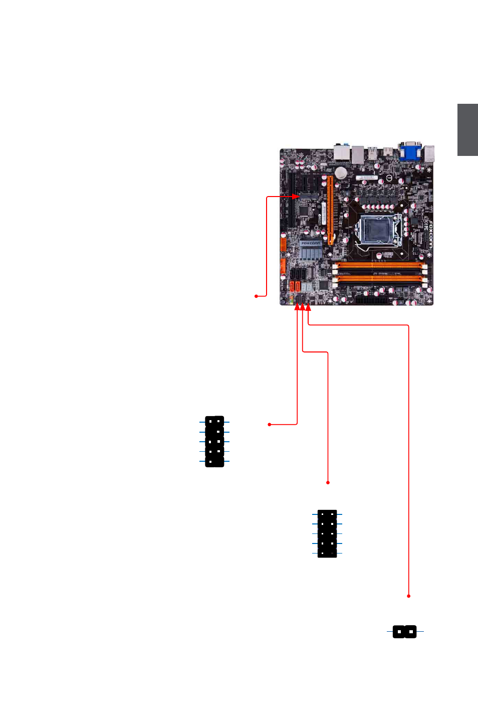
mSATA Connector : mSATA
The connector is used to connect mSATA device.
IrDA Connector : CIR
This connector supports infrared wireless transmit-
ting and receiving device. (Only support under Win
7)
CoM Connector : CoM1
This motherboard supports one serial RS232 COM
port for legacy compatibility. User must purchase an-
other RS232 cable with a 9-pin D-sub connector at
one end to connect with the external RS232 device
and another end with 10-pin female connector to con-
nect with COM1 connector in the motherboard.
Chassis Intruder Alarm Connector : INTR
The connector can be connected to a security
switch on the chassis. The system can detect
the chassis intrusion through the function of this
connector. If eventually the chassis is closed, the
system will send a message out.
RLSD
SOUT
RI
GND
RTS
DSR
DTR
CTS
EMPTY
SIN
1 2
10
9
COM1
CIR
+5V
EMPTY
NC
GND
NC
+5VSB
CIRRX
GND
CIRTX
EMPTY
1 2
9 10
INTR
GND
INTRUDERJ
1